My Cart
0 items
Genuine Automation Parts | Worldwide Express Delivery | 12-Month Warranty — [GET A QUOTE]

Configured for network management in V-net repeater systems, the Yokogawa AIP171 (AIP171 Transceiver Control Module) provides direct physical execution of transceiver monitoring and signal integrity management across control network segments.
...Availability: Low stock: 99 left
Reliable Worldwide Delivery
30-Day Money-Back Guarantee
Need more details? Read our fullShipping PolicyandRefund Policy.


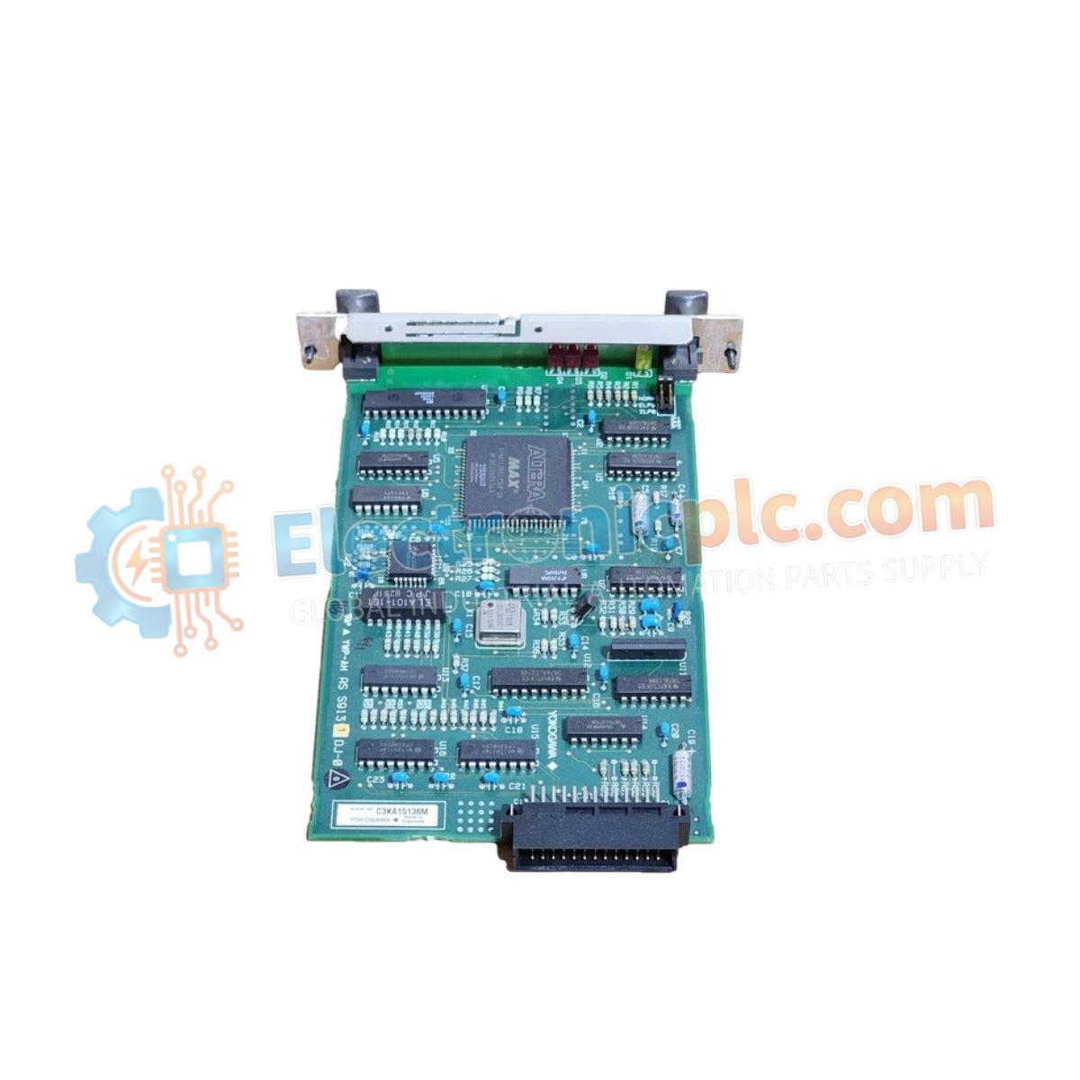
Configured for network management in V-net repeater systems, the Yokogawa AIP171 (AIP171 Transceiver Control Module) provides direct physical execution of transceiver monitoring and signal integrity management across control network segments.
| Parameter | Specification |
|---|---|
| Model | AIP171 |
| Brand | Yokogawa |
| Origin | Japan |
| Weight | 1 kg |
| Dimensions | 100 mm x 200 mm x 30 mm |
| Operating Temp | 0 deg C to 50 deg C |
| Power Consumption | 24 VDC / 20 W |
| Control Capacity | Up to 16 transceivers |
| Compatibility | Electrical and optical transceivers |
The AIP171 module serves as the supervisory controller for transceiver arrays, utilizing internal logic to perform active fault detection and signal isolation. By monitoring the status of both electrical and optical transceiver interfaces, the module ensures that localized hardware failures do not propagate to the broader V-net backbone. The integration of configurable DIP switches allows for precise protocol alignment and network timing adjustments, ensuring deterministic packet delivery and minimal latency within the CENTUM control architecture.
Q: How are the DIP switches configured on the AIP171?
A: DIP switch settings must be adjusted according to the specific network topology and the number of active transceivers as defined in the system engineering documentation. Settings must be verified against the site-specific network map to avoid addressing conflicts.
Q: Can the module manage a mix of optical and electrical transceivers simultaneously?
A: Yes, the module is designed for heterogeneous transceiver environments. It maintains separate signal integrity checks for both physical media types to ensure uniform performance across the V-net repeater segment.


