My Cart
0 items
Genuine Automation Parts | Worldwide Express Delivery | 12-Month Warranty — [GET A QUOTE]

Configured for high-speed network integration within Yokogawa control platforms, the YOKOGAWA AIP503-S1 (AIP503-S1 Coupler Module) provides direct physical signal transmission and data bridging between field instrumentation and V-NET process control...
Availability: Low stock: 99 left
Reliable Worldwide Delivery
30-Day Money-Back Guarantee
Need more details? Read our fullShipping PolicyandRefund Policy.


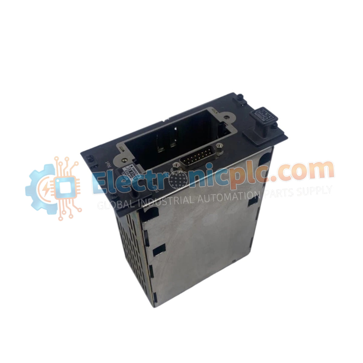
Configured for high-speed network integration within Yokogawa control platforms, the YOKOGAWA AIP503-S1 (AIP503-S1 Coupler Module) provides direct physical signal transmission and data bridging between field instrumentation and V-NET process control networks. This hardware component serves as the primary gateway utilized to execute network communication synchronization across CENTUM CS and CENTUM VP platforms.
| Parameter | Specification |
|---|---|
| Model | AIP503-S1 |
| Brand | Yokogawa |
| Origin | Japan |
| Weight | 1.8 kg |
| Dimensions | 7.6 cm x 15.2 cm x 17.8 cm |
| Operating Temp | Standard industrial ambient range |
| Power Consumption | 24 VDC |
| Network Type | V-NET (10BASE-5) |
The AIP503-S1 manages the V-NET (10BASE-5) communication protocol to ensure deterministic data exchange across the distributed control architecture. By acting as a bridge, the module performs the necessary electrical and logical signal conversion required for high-velocity transmission between the field-level data bus and the system network. This ensures low-latency polling of field devices and robust performance in real-time control applications.
Q: Does the AIP503-S1 require a specific transceiver for the V-NET connection?
A: The module is designed for 10BASE-5 connectivity; ensure that the appropriate AUI (Attachment Unit Interface) cables and external transceivers are utilized if the network backbone requires a physical medium transition.
Q: How is the module grounded to the cabinet chassis?
A: The AIP503-S1 utilizes the mounting fasteners and dedicated backplane ground lugs to establish a chassis bond. Ensure these connections are clean and tightened to provide an effective path for transient electrical noise.


