My Cart
0 items
Genuine Automation Parts | Worldwide Express Delivery | 12-Month Warranty — [GET A QUOTE]

Configured for high-speed signal distribution within the CENTUM VP control architecture, the YOKOGAWA AIP571 S2 (AIP571 Electrical Transceiver RIO I/O Module) provides direct physical and electrical execution of fiber-optic data...
Availability: Low stock: 99 left
Reliable Worldwide Delivery
30-Day Money-Back Guarantee
Need more details? Read our fullShipping PolicyandRefund Policy.


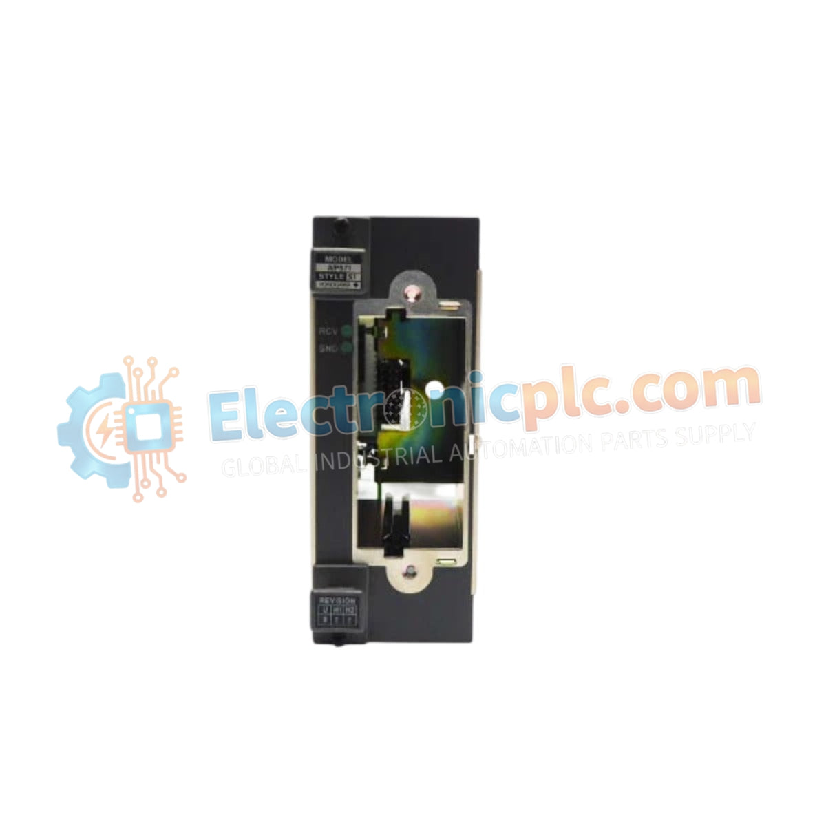
Configured for high-speed signal distribution within the CENTUM VP control architecture, the YOKOGAWA AIP571 S2 (AIP571 Electrical Transceiver RIO I/O Module) provides direct physical and electrical execution of fiber-optic data transmission between remote I/O modules and Field Control Units (FCU).
The AIP571 S2 denotes the specific hardware revision optimized for long-distance optical fiber interfacing. No further functional variants or modular sub-codes are designated for this hardware type in standard documentation.
| Parameter | Specification |
|---|---|
| Model | AIP571 S2 |
| Brand | YOKOGAWA |
| Origin | Janpan |
| Weight | 1.5 kg |
| Dimensions | 160 mm x 60 mm x 30 mm |
| Operating Temp | -20 to 70 deg C |
| Power Consumption | 20 W |
| Power Supply | 24 VDC |
| Data Transfer Rate | 100 Mbps |
| Communication Medium | Optical Fiber |
The AIP571 S2 architecture utilizes optical fiber media to provide electrical isolation between distant process segments, preventing ground potential shift issues common in geographically distributed control systems. The module supports redundant communication paths, ensuring that a single-cable failure does not compromise the deterministic data transfer required for CENTUM VP operations. By maintaining a transmission speed of 100 Mbps, the module minimizes protocol latency between the Field Control Unit and the remote I/O rack.
Q: Does the AIP571 S2 require external configuration for redundancy management?
A: Redundancy logic is managed by the Field Control Unit (FCU) firmware. When dual modules are installed with redundant optical fiber paths, the system automatically arbitrates between paths to ensure continuous communication.
Q: Is the 24 VDC power supply requirement sensitive to voltage fluctuations?
A: The module is designed to operate within standard industrial 24 VDC ranges. However, to maintain the 100 Mbps transmission stability, it is recommended to use a regulated, low-noise DC power source to prevent ripple interference on the transceiver circuitry.


