
My Cart
0 items
Genuine Automation Parts | Worldwide Express Delivery | 12-Month Warranty — [GET A QUOTE]

The Yokogawa AKB331-M007 (AKB331-M007 Signal Cable) operates as a dedicated hardware component for deterministic signal transmission between field interface modules and terminal boards within Yokogawa process control systems.
Availability: In stock
Reliable Worldwide Delivery
30-Day Money-Back Guarantee
Need more details? Read our fullShipping PolicyandRefund Policy.
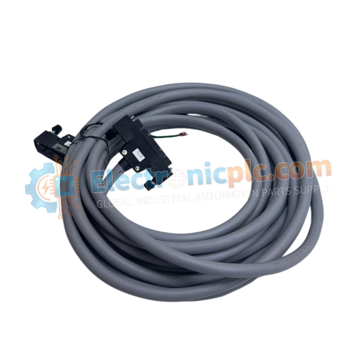
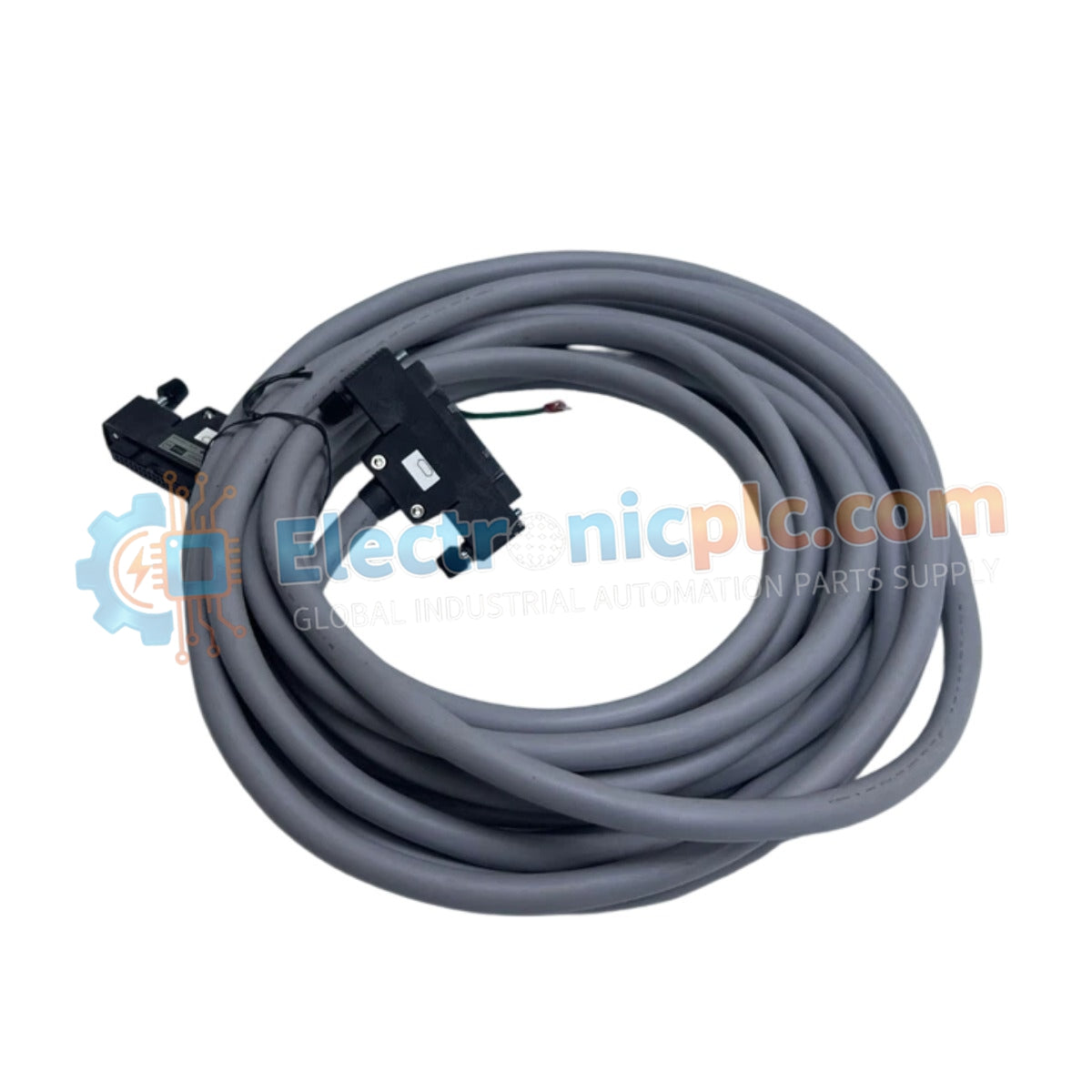
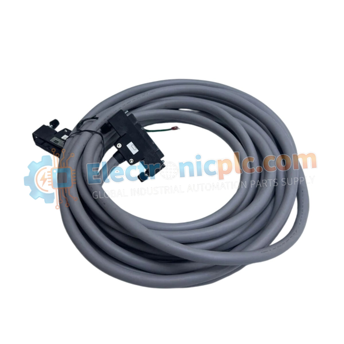
The Yokogawa AKB331-M007 (AKB331-M007 Signal Cable) operates as a dedicated hardware component for deterministic signal transmission between field interface modules and terminal boards within Yokogawa process control systems.
| Parameter | Specification |
|---|---|
| Model | AKB331-M007 |
| Brand | Yokogawa |
| Origin | japan |
| Weight | 1.23kg |
| Dimensions | 7.0 m (nominal length) |
| Operating Temp | Not Specified |
| Power Consumption | N/A (Passive component) |
| Cable Type | Multi-core shielded signal cable |
| Connector Type | System-specific multi-pin interface |
The AKB331-M007 facilitates the interconnection of I/O modules and remote terminal boards, ensuring deterministic signal transit across the control cabinet architecture. The cable utilizes high-density shielding to minimize crosstalk and electromagnetic interference (EMI) impacts, which is necessary for maintaining the integrity of low-level analog and digital signals. Its internal wiring architecture is designed to support high-velocity bus communication and I/O density scaling, ensuring that signal attenuation is kept within acceptable limits for real-time process monitoring. The mechanical design of the connectors ensures robust contact, preventing signal degradation caused by vibration in industrial environments.
Q: Is the AKB331-M007 cable suitable for use in cable trays with high-voltage power lines?
A: No. To maintain signal integrity and comply with standard industrial installation practices, this signal cable must be routed through dedicated cable trays separated from high-voltage AC or DC power cabling to avoid induced noise.
Q: Can the cable be shortened or extended in the field?
A: Modification of the AKB331-M007 is not recommended, as it can compromise the shielding integrity and connector pin-out configuration, potentially leading to intermittent communication errors or system faults.


