
My Cart
0 items
Genuine Automation Parts | Worldwide Express Delivery | 12-Month Warranty — [GET A QUOTE]

Configured for high-density signal interconnects in safety and control systems, the Yokogawa AKB331-M020 (AKB331-M020) provides direct physical/electrical execution of 50-pin to 50-pin signal transmission between interface modules and terminal boards.
...Availability: Low stock: 99 left
Reliable Worldwide Delivery
30-Day Money-Back Guarantee
Need more details? Read our fullShipping PolicyandRefund Policy.


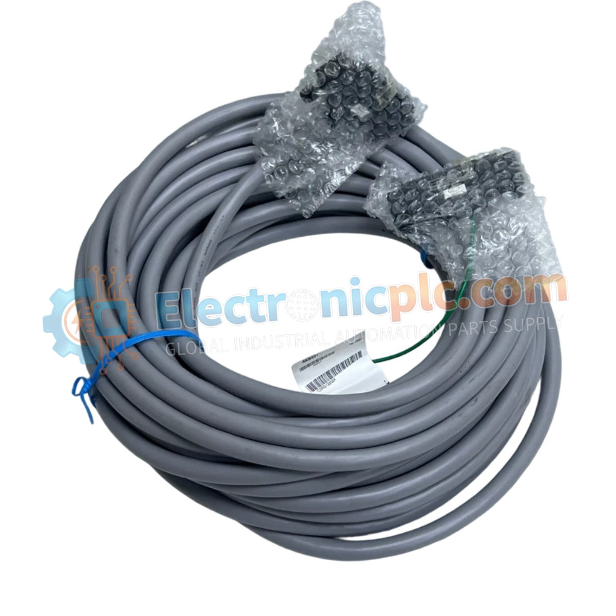
Configured for high-density signal interconnects in safety and control systems, the Yokogawa AKB331-M020 (AKB331-M020) provides direct physical/electrical execution of 50-pin to 50-pin signal transmission between interface modules and terminal boards.
| Parameter | Specification |
|---|---|
| Model | AKB331-M020 |
| Brand | Yokogawa |
| Origin | Japan |
| Weight | 1.5 kg |
| Dimensions | 20 meter length |
| Operating Temp | -20 to 80 deg C |
| Insulation Resistance | 100 M Ohm or more at 500 V DC |
| Voltage Rating | 250 V AC |
| Cable Diameter | 6.8 mm |
| Connector Configuration | 50-pin to 50-pin |
The cable is engineered to maintain signal fidelity for specific Yokogawa system modules, including the SDV144, SDV531, SDV53A, SDV541, and SAT145. The design incorporates robust insulation materials capable of withstanding industrial temperature fluctuations up to 80 deg C. By providing a matched impedance path for high-density I/O arrays, the cable ensures reliable communication between the primary control hardware and the field terminal board, minimizing the risk of signal attenuation or crosstalk during high-speed data transmission.
Q: Can this 20-meter cable be used in outdoor environments or high-moisture areas?
A: The AKB331 series is designed for deployment within control room cabinets and standard industrial enclosures. Exposure to direct outdoor weather conditions or persistent moisture may compromise the insulation resistance and is not recommended.
Q: Is it permissible to bundle this signal cable with high-voltage power lines?
A: No, signal cables must be routed in dedicated, grounded conduits or cable trays separate from high-voltage AC lines to mitigate electromagnetic interference (EMI) that can degrade I/O accuracy.


