My Cart
0 items
Genuine Automation Parts | Worldwide Express Delivery | 12-Month Warranty — [GET A QUOTE]

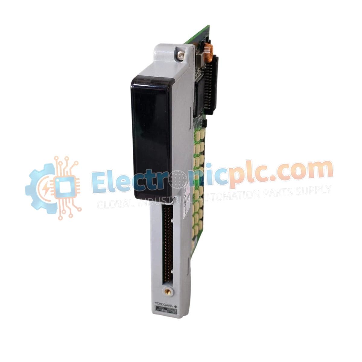
Configured for discrete signal transmission in industrial control platforms, the Alstom ADM52C-2-S3 (ADM52C Output Module) provides direct physical/electrical execution of digital output state switching.
| Parameter | Specification |
|---|---|
| Model | ADM52C-2-S3 |
| Brand | Yokogawa |
| Origin | United States |
| Weight | 0.6 kg |
| Dimensions | 2.5 cm x 22.9 cm x 7.6 cm |
| Operating Temp | Standard industrial range |
| Power Consumption | System-dependent load |
| Output Type | Discrete output |
The ADM52C-2-S3 serves as a dedicated hardware component for executing output switching operations across control platforms. This module requires verified firmware flash compatibility with the host controller backplane to ensure deterministic communication. Because the module is designed for integration into dense I/O racks, users must manage the backplane bus communication velocity to avoid signal latency during high-speed cycle updates. The hardware architecture utilizes standard bus signaling to distribute output states; therefore, firmware updates should be coordinated with the central processor cycle to prevent synchronization errors during active control sequences.
Q: Is the ADM52C-2-S3 compatible with previous revision firmware?
A: Compatibility is contingent upon the host backplane revision. Always verify the firmware flash compatibility matrix provided in the controller system manual before deploying the module into an existing rack.
Q: What are the restrictions regarding I/O density on the host backplane?
A: The module occupies a specific I/O address space. Ensure that the total I/O density scaling does not exceed the capacity of the host rack power supply or the communication bandwidth limits of the backplane bus.