My Cart
0 items
Genuine Automation Parts | Worldwide Express Delivery | 12-Month Warranty — [GET A QUOTE]

Configured for relay signal switching in control networks, the Yokogawa AMN21 (AMN21 Relay Nest) provides direct physical/electrical execution of modular backplane routing for relay I/O modules across CENTUM CS 1000,...
Availability: Low stock: 99 left
Reliable Worldwide Delivery
30-Day Money-Back Guarantee
Need more details? Read our fullShipping PolicyandRefund Policy.


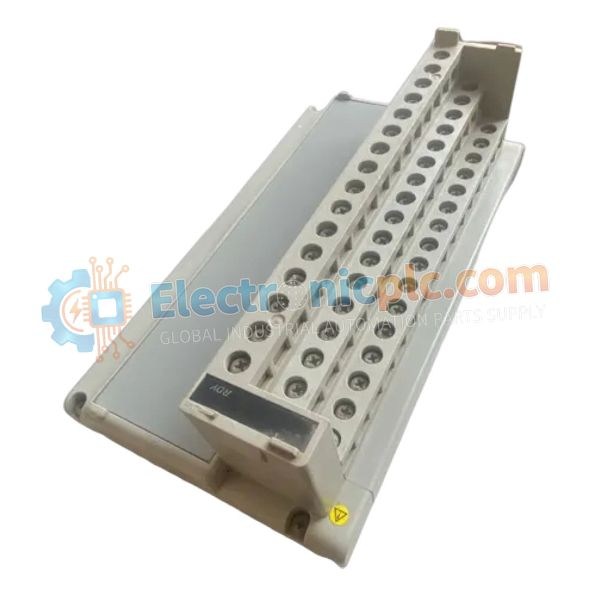
Configured for relay signal switching in control networks, the Yokogawa AMN21 (AMN21 Relay Nest) provides direct physical/electrical execution of modular backplane routing for relay I/O modules across CENTUM CS 1000, CS 3000, and CENTUM VP platforms.
| Parameter | Specification |
|---|---|
| Model | AMN21 |
| Brand | Yokogawa |
| Origin | Japan |
| Weight | 1.5 kg |
| Dimensions | Standard Yokogawa relay nest dimensions |
| Operating Temp | -10 to 60 deg C |
| Storage Temp | -20 to 70 deg C |
| Power Consumption | 24 VDC, 110 VAC, or 220 VAC |
| Relay Capacity | 2 A at 250 VAC / 30 VDC |
| Humidity | 10% to 90% RH (non-condensing) |
The AMN21 relay nest architecture provides a robust interface for high-voltage and high-current discrete signal switching. By integrating individual relay slots within a common backplane, the nest facilitates the galvanic isolation of field-side circuits from the low-voltage logic control bus. This design minimizes the risk of back-feed interference and ensures that inductive switching transients are suppressed, preserving the operational longevity of both the field instrumentation and the controller interface modules.
Q: Does the AMN21 relay nest support mixed-voltage load configurations?
A: The nest allows for multiple relay modules to be installed; however, each channel must be wired in accordance with the specific voltage rating of the module and the local safety insulation standards for the cabinet.
Q: Is the AMN21 nest suitable for high-frequency switching operations?
A: While designed for industrial process control, the mechanical lifespan of the relays is limited by their duty cycle. For high-frequency switching, ensure that the application does not exceed the mechanical cycle limits specified for the installed relay modules.


