My Cart
0 items
Genuine Automation Parts | Worldwide Express Delivery | 12-Month Warranty — [GET A QUOTE]

Configured for high-density signal integration in control networks, the Yokogawa AMN51 (AMN51 Nest for Communication Cards) provides direct physical/electrical execution of modular backplane routing for communication components within Yokogawa field...
Availability: Low stock: 99 left
Reliable Worldwide Delivery
30-Day Money-Back Guarantee
Need more details? Read our fullShipping PolicyandRefund Policy.
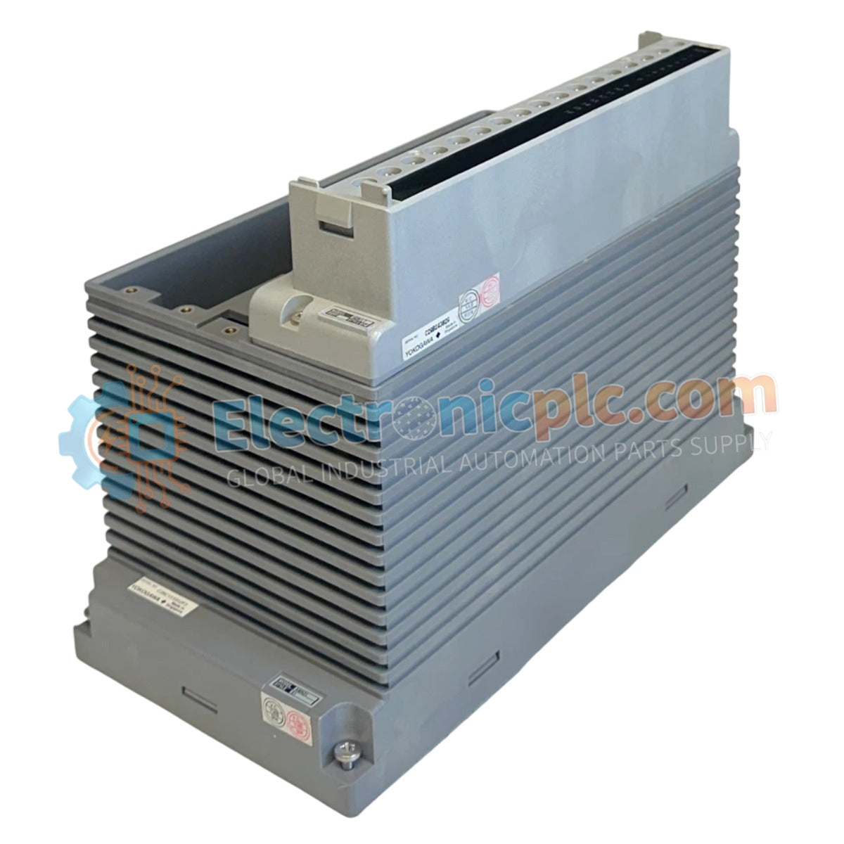
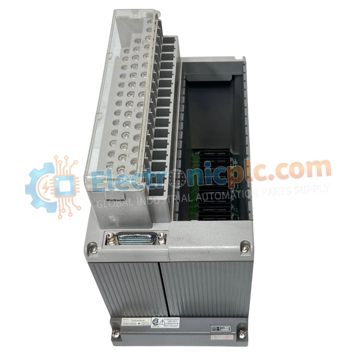
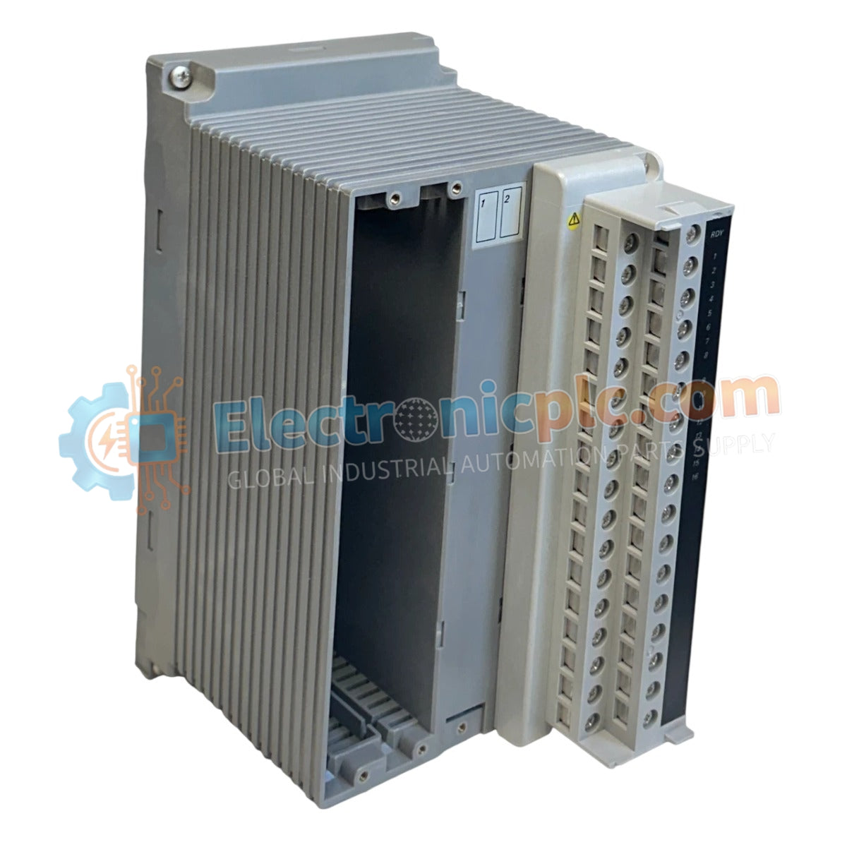
Configured for high-density signal integration in control networks, the Yokogawa AMN51 (AMN51 Nest for Communication Cards) provides direct physical/electrical execution of modular backplane routing for communication components within Yokogawa field control stations.
| Parameter | Specification |
|---|---|
| Model | AMN51 |
| Brand | Yokogawa |
| Origin | Japan |
| Weight | 2.5 kg |
| Dimensions | 137.5 mm x 225 mm x 254 mm |
| Operating Temp | 0 to 50 deg C |
| Power Supply | 5.0 VDC |
| Power Source | AND50, ANS50, AND20, ANS20, or PFCS/PFCD |
| Installation | Node Interface Unit, I/O Expansion Rack, PFCS/PFCD |
The AMN51 nest serves as the foundational interface for communication cards in Yokogawa DCS architectures. By utilizing a stable 5.0 VDC supply derived from node interface units or field control stations (PFCS/PFCD), the nest ensures consistent power delivery to maintain communication card throughput and signal integrity. The mechanical design facilitates integration into various field control station configurations, supporting high-speed data exchange protocols required for real-time process monitoring and control.
Q: Is the AMN51 nest compatible with power sources other than the specified AND/ANS series nodes?
A: The nest is strictly engineered for 5.0 VDC input from the listed node interface units or PFCS/PFCD stations; use of unauthorized power sources may cause hardware failure or communication instability.
Q: Can the AMN51 nest be mounted in an I/O expansion rack without a node interface unit?
A: The nest is designed for use within I/O expansion racks or node interface units, provided the rack provides the necessary 5.0 VDC bus connection and electrical isolation required by the communication cards.


