
My Cart
0 items
Genuine Automation Parts | Worldwide Express Delivery | 12-Month Warranty — [GET A QUOTE]

The YOKOGAWA F3AD04-5V, also cataloged as the F3AD04 analog input module, operates as a dedicated hardware component for high-density analog signal acquisition within F3 series programmable logic controller platforms.
Availability: In stock
Reliable Worldwide Delivery
30-Day Money-Back Guarantee
Need more details? Read our fullShipping PolicyandRefund Policy.


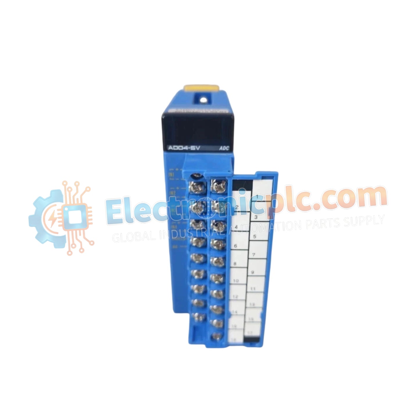
The YOKOGAWA F3AD04-5V, also cataloged as the F3AD04 analog input module, operates as a dedicated hardware component for high-density analog signal acquisition within F3 series programmable logic controller platforms.
F3: Series prefix indicating compatibility with standard F3 backplane rack systems.
AD: Analog-to-digital input function designation.
04: Four differential input channels configuration.
5V: 5 VDC backplane power supply operation.
| Parameter | Specification |
| Model | F3AD04-5V |
| Brand | YOKOGAWA |
| Origin | Singapore |
| Weight | 0.2 kg |
| Dimensions | 28.9 mm (W) x 100 mm (H) x 106.1 mm (D) |
| Operating Temp | 0 deg C to 55 deg C |
| Power Consumption | 5 VDC nominal |
| Input Channels | 4 Differential |
The F3AD04-5V is engineered for integration into deterministic control networks, ensuring precise timing for analog-to-digital conversion cycles. The module architecture supports high-speed backplane bus communication, enabling the PLC processor to synchronize data acquisition with real-time logic execution. The design utilizes high-impedance differential inputs to minimize loading effects on field instrumentation, maintaining signal accuracy in complex I/O density scaling applications.
Q: Does the F3AD04-5V support hot-swapping on the F3 backplane?
A: No, the module does not support hot-swapping. The rack power must be cycled off prior to module insertion or removal to prevent electrical arcing and backplane bus communication errors.
Q: Are the four differential input channels electrically isolated from each other?
A: The F3AD04-5V features differential inputs; however, consult the technical manual for specific galvanic isolation ratings. In applications with high common-mode voltages, external signal isolators are required to protect the module input circuitry.
Verify that the F3 base rack is properly grounded to the cabinet's protective earth bus to ensure electromagnetic compatibility and personnel safety.
Align the module with the intended slot guides on the backplane rack. Apply consistent pressure until the module is fully seated and the locking lever is engaged.
For differential signals, connect both the positive and negative signal leads to the designated terminal block. Ensure that twisted-pair, shielded cabling is utilized to minimize EMI.
Ground the cable shield at a single termination point, preferably at the cabinet's instrument earth bar, to prevent ground loops that could introduce signal noise.
After installation, perform a software configuration check to ensure the CPU accurately maps the input channels and that the converted digital values correlate to the field signal levels.


