
My Cart
0 items
Genuine Automation Parts | Worldwide Express Delivery | 12-Month Warranty — [GET A QUOTE]

Configured for high-speed data exchange in FIO (Fieldbus I/O) platforms, the YOKOGAWA ANR10D-410 (ANR10D Node Interface Unit) provides direct physical/electrical execution. This hardware component manages the ER Bus protocol interface,...
Availability: In stock
Reliable Worldwide Delivery
30-Day Money-Back Guarantee
Need more details? Read our fullShipping PolicyandRefund Policy.
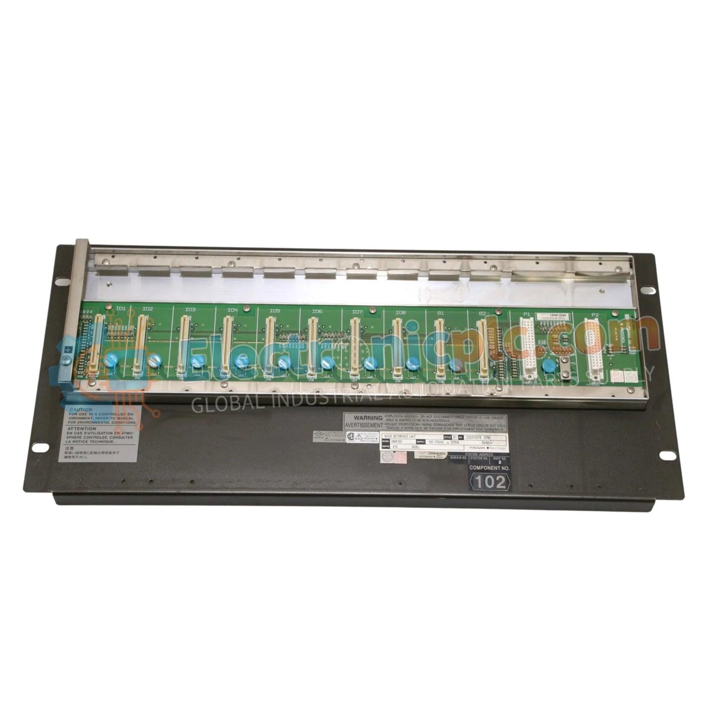

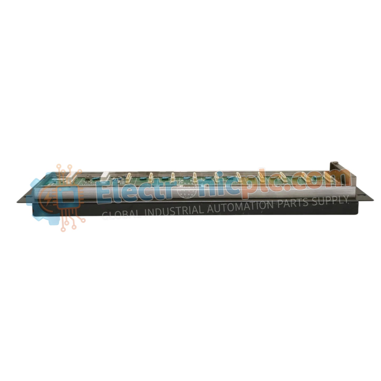
Configured for high-speed data exchange in FIO (Fieldbus I/O) platforms, the YOKOGAWA ANR10D-410 (ANR10D Node Interface Unit) provides direct physical/electrical execution. This hardware component manages the ER Bus protocol interface, facilitating deterministic communication between remote node units and the central field control station within Yokogawa distributed control system architectures.
| Parameter | Specification |
|---|---|
| Model | ANR10D-410 |
| Brand | YOKOGAWA |
| Origin | JAPAN |
| Weight | 2.6 kg |
| Dimensions | 17.8 cm x 22.9 cm x 5.1 cm |
| Operating Temp | -20 to 70 deg C |
| Power Consumption | 132 W (Max, 24 VDC @ 5.5 A) |
| Communication | ER Bus protocol |
| Compatibility | FIO components |
The ANR10D-410 acts as the signal coordination hub for I/O node connectivity, ensuring that data transmission across the ER Bus remains consistent with the system scan cycles. The unit incorporates galvanic isolation to maintain loop integrity and prevent electrical noise propagation from field-side segments to the internal system backplane. This interface ensures that process control data is prioritized and synchronized across the ER Bus, maintaining the deterministic timing required for high-availability distributed control operations.
Q: Does the ANR10D-410 interface unit require redundant power connections for high-availability setups?
A: Yes, in configurations requiring high availability, dual power feeds should be connected to the module’s redundant input terminals to ensure operation during a single power supply unit failure.
Q: Is this unit compatible with existing FIO base plates used in legacy Centum VP systems?
A: The ANR10D-410 is specifically engineered for FIO-compliant systems; ensure that the base plate revision and firmware version support the specific ER Bus interface protocol requirements of the ANR10D.


