My Cart
0 items
Genuine Automation Parts | Worldwide Express Delivery | 12-Month Warranty — [GET A QUOTE]

Configured for high-density field control within CENTUM VP architectures, the Yokogawa ARM55W-000 (ARM55W-000 Relay Output Board) provides direct physical signal execution for 32-channel wet contact outputs.
Availability: In stock
Reliable Worldwide Delivery
30-Day Money-Back Guarantee
Need more details? Read our fullShipping PolicyandRefund Policy.


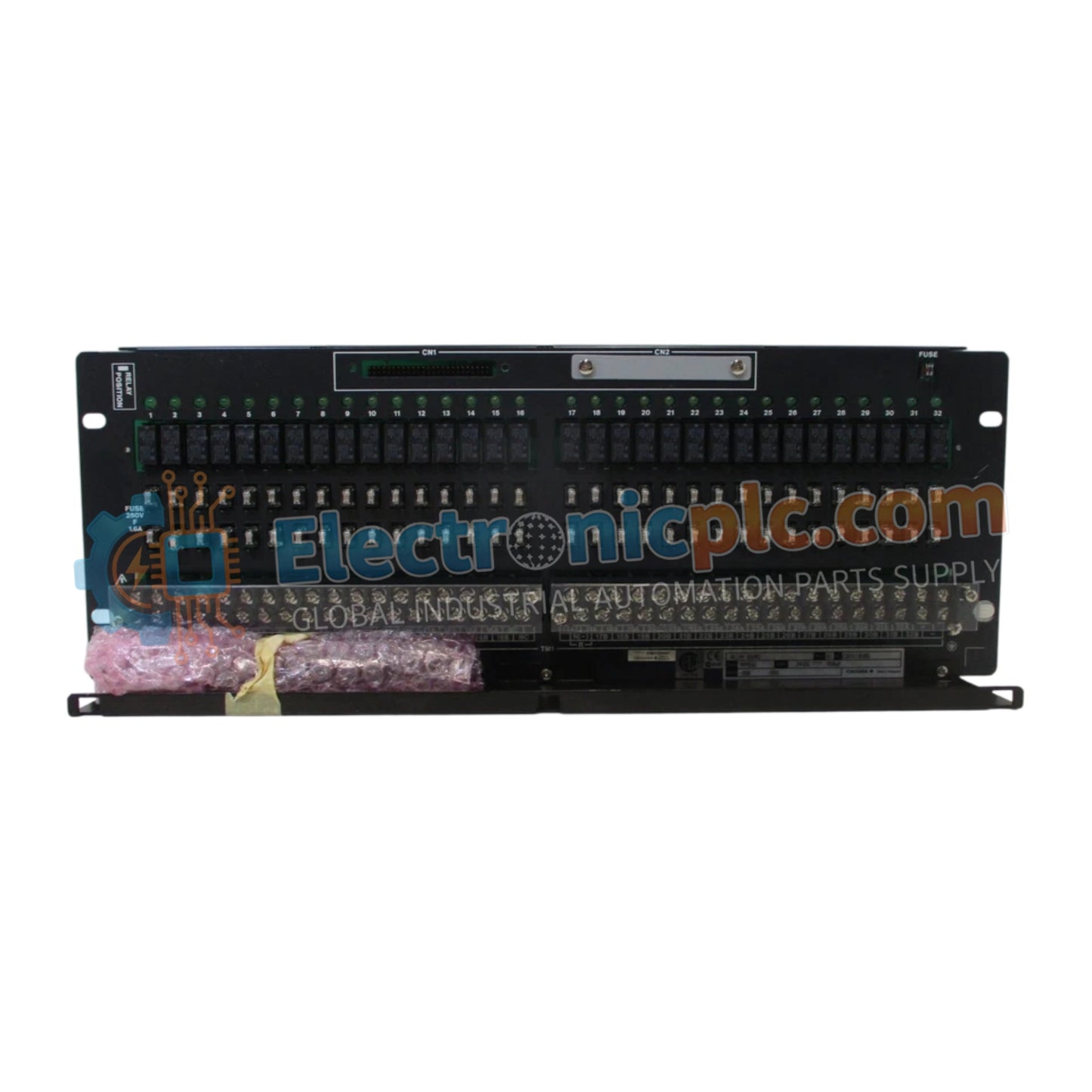
Configured for high-density field control within CENTUM VP architectures, the Yokogawa ARM55W-000 (ARM55W-000 Relay Output Board) provides direct physical signal execution for 32-channel wet contact outputs.
| Parameter | Specification |
|---|---|
| Model | ARM55W-000 |
| Brand | Yokogawa |
| Weight | 2.6 kg |
| Dimensions | 482.6 mm x 177 mm (4U) |
| Operating Temp | 0 deg C to +50 deg C |
| Output Points | 32 channels |
| Output Type | Wet contact (single or dual-redundant) |
| Contact Rating | 250 V AC 0.6 A / 30 V DC 0.6 A / 125 V DC 0.1 A |
| Terminal Type | M4 screw terminals |
| Compatibility | ADV551, ADV561 |
The ARM55W-000 is engineered to interface directly with Yokogawa Field I/O (FIO) modules such as the ADV551 and ADV561. This board provides the necessary electrical isolation between the control system and field-side devices, supporting high-reliability applications including solenoid control, alarm initiation, and process interlocks. The dual-line power supply configuration per 16 points allows for flexible redundancy strategies, ensuring that a fault in one power segment does not compromise the entire output board. The assembly features an insulation resistance of 10 MΩ and a 2 kV withstand voltage, protecting the DCS processor from electrical transients originating in the field environment.
Q: Can the ARM55W-000 be used for safety-critical interlock applications?
A: The board is designed for industrial process control with standard certifications. For safety-critical functions requiring specific SIL ratings, ensure the application design aligns with the ProSafe-RS platform or equivalent safety-instrumented system requirements.
Q: What is the benefit of the dual-line power configuration?
A: The dual-line power architecture allows for redundant power supply input. If one power source fails, the remaining line ensures continued operation of the designated output points, enhancing system availability in mission-critical applications.


