
My Cart
0 items
Genuine Automation Parts | Worldwide Express Delivery | 12-Month Warranty — [GET A QUOTE]

Configured for analog signal acquisition in Field Integrated Operation (FIO) platforms, the Yokogawa AS1133-H00 (AS1133-H00 Analog Input Module) provides direct physical/electrical execution of 8-channel 4-20 mA input sensing.
Availability: Low stock: 99 left
Reliable Worldwide Delivery
30-Day Money-Back Guarantee
Need more details? Read our fullShipping PolicyandRefund Policy.
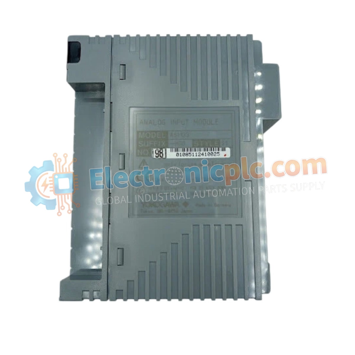
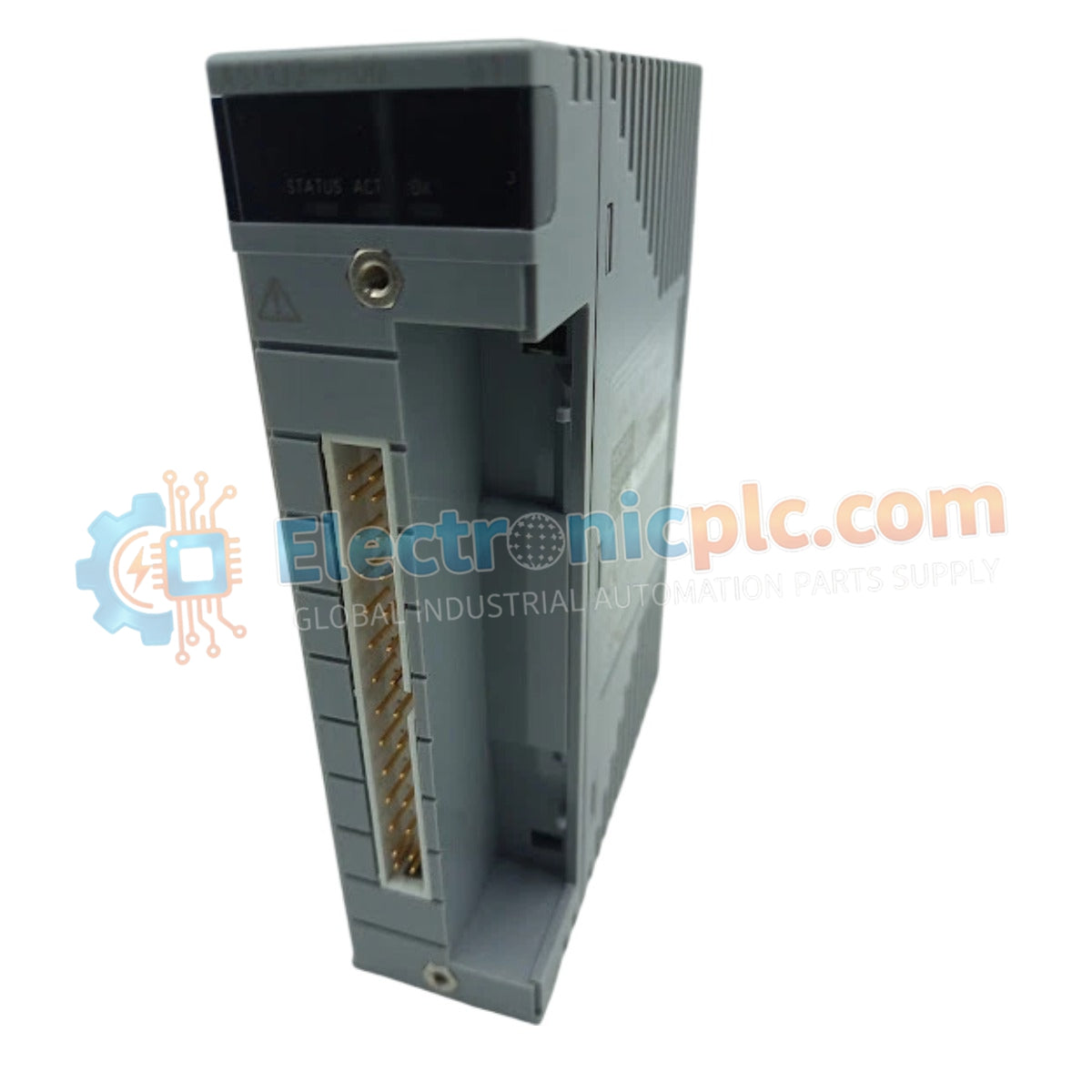
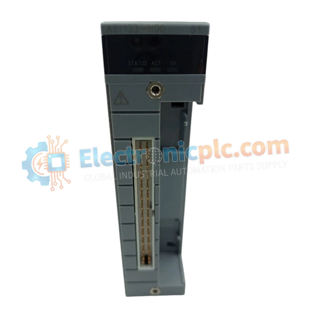
Configured for analog signal acquisition in Field Integrated Operation (FIO) platforms, the Yokogawa AS1133-H00 (AS1133-H00 Analog Input Module) provides direct physical/electrical execution of 8-channel 4-20 mA input sensing.
| Parameter | Specification |
|---|---|
| Model | AS1133-H00 |
| Brand | Yokogawa |
| Origin | Japan |
| Weight | 0.5 kg |
| Dimensions | 3.8 cm x 12.7 cm x 15.2 cm |
| Operating Temp | Industrial grade (consult FIO system manual) |
| Power Consumption | Refer to FIO system power budget |
| Input Channels | 8 |
| Input Type | 4-20 mA DC |
| Isolation | Channel-to-channel isolated |
The module functions as an interface for field-mounted transmitters, including pressure transducers, temperature sensors, and flow meters. To maintain process data integrity in demanding environments, the design utilizes channel-to-channel isolation, which mitigates common-mode noise and ground loops between disparate field loops. The integrated safety barrier design supports deployment in hazardous area installations, providing intrinsic protection for the field side while maintaining high-resolution signal conversion for the FIO control bus.
Q: Does the integrated safety barrier design require additional external barriers for hazardous zone deployment?
A: The module is engineered with built-in safety barrier functionality. Verify that the specific hazardous area classification and zone requirements match the module's safety rating as documented in the technical manual.
Q: Can these channels be configured for voltage inputs in addition to 4-20 mA?
A: The hardware architecture is optimized for 4-20 mA current loop sensing. Refer to the system configuration guide to determine if shunt resistors or alternative software-defined modes support voltage input ranges.


