Skip to product information
1 of 1

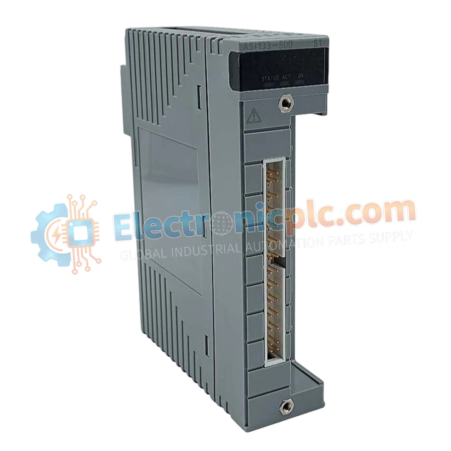
ASI133-S00/SA3S0 Analog Input Module Yokogawa

ASI133-S00/SA3S0 Analog Input Module Yokogawa

Configured for precision signal acquisition in hazardous area control networks, the Yokogawa ASI133-S00/SA3S0 (ASI133-S00 Analog Input Module) provides direct physical/electrical execution of intrinsically safe monitoring for field instrumentation.

Suffix Breakdown...

21 people are viewing this right now

AvailabilityIn stock

SKU: ASI133-S00/SA3S0
Vendor: Yokogawa
Related Series:

Shipping & Returns

Reliable Worldwide Delivery

  • Carriers: Shipped via DHL, FedEx, UPS, or USPS.
  • Dispatch: Orders processed in 1-2 business days and dispatched within 3-5 business days.
  • Tracking: Full tracking details provided via email upon shipment.

30-Day Money-Back Guarantee

  • Guarantee: 30-day return window for in-stock, factory-sealed products.
  • Condition: Items must be unopened, unused, and in original packaging.
  • Authenticity: We guarantee 100% original and authentic hardware.

Need more details? Read our fullShipping PolicyandRefund Policy.
Authenticity & Warranty

  • Genuine Guarantee: We supply only 100% original, brand-new, and factory-sealed industrial automation parts.
  • Full Coverage: Every component is backed by a 12-month comprehensive warranty from the date of purchase.
  • Traceability: All products come with original factory documentation and accessories for full industrial compliance.

Technical Support & Sourcing

  • Expert Assistance: Our technical team provides free consultation to help you verify compatibility for DCS and PLC systems.
  • Rare Part Sourcing: Specializing in obsolete and hard-to-find components from Allen-Bradley, Siemens, ABB, HIMA, and more.
  • Bulk Inquiries: Contact us at pambo@5gplc.com for volume pricing or customized project quotes.
View full product details

Configured for precision signal acquisition in hazardous area control networks, the Yokogawa ASI133-S00/SA3S0 (ASI133-S00 Analog Input Module) provides direct physical/electrical execution of intrinsically safe monitoring for field instrumentation.

Suffix Breakdown & Model Matrix

  • ASI133-S00: Base module designation for 8-channel analog input functionality.
  • SA3S0: Suffix indicating integrated Zener barrier circuitry optimized for hazardous area interface compliance and intrinsic safety certification.

Hardware Specifications

Parameter Specification
Model ASI133-S00/SA3S0
Brand Yokogawa
Origin Japan
Weight 0.4 kg
Dimensions 3.0 cm x 13.0 cm x 13.5 cm
Operating Temp -20 deg C to 60 deg C
Power Consumption 5 W (maximum from backplane)
Input Channels 8 channels
Signal Range 4 to 20 mA DC
Resolution 16-bit
Accuracy +/- 0.1 % of span
Scan Rate 100 ms per channel

Channel-to-Channel Isolation and Intrinsic Safety

The ASI133-S00/SA3S0 module utilizes integrated galvanic and Zener barrier technologies to enforce intrinsic safety for field-connected instruments. Each of the 8 input channels is isolated from the system backplane and neighboring channels to prevent common-mode noise propagation and ground loop currents. This isolation architecture ensures that faults occurring within field-level loops do not propagate to the DCS processor bus. The module meets ATEX/IECEx standards for Zone 0/1 applications, maintaining a strictly regulated energy limit at the field terminals to prevent ignition sources in hazardous environments.

Frequently Asked Questions

Q: Can the ASI133-S00/SA3S0 support hot-swapping during active system operation?

A: No. The module is not designed for hot-swap capability. Power must be removed from the local node backplane before module extraction to prevent transient voltage spikes on the analog input loops.

Q: Is external barrier hardware required for this module?

A: No. The SA3S0 specification includes built-in Zener barrier components, allowing for direct connection to field transmitters located in classified hazardous areas.

Field Installation Guidelines

  1. Ensure the control cabinet is properly grounded and that the module is installed in an environment within the specified ambient temperature range of -20 deg C to 60 deg C.
  2. Verify that the system backplane is de-energized prior to seating the module to avoid damage to the communication pins.
  3. Utilize shielded twisted-pair cabling for all field signal inputs; terminate the shield at the cabinet earth bus bar to maximize noise immunity.
  4. Ensure separation between intrinsically safe (IS) wiring and non-IS wiring within the cable ducting to comply with regional hazardous area wiring standards.
  5. Tighten all terminal screws to the specified torque to prevent intermittent signal loss or contact resistance variations during plant operation.