My Cart
0 items
Genuine Automation Parts | Worldwide Express Delivery | 12-Month Warranty — [GET A QUOTE]

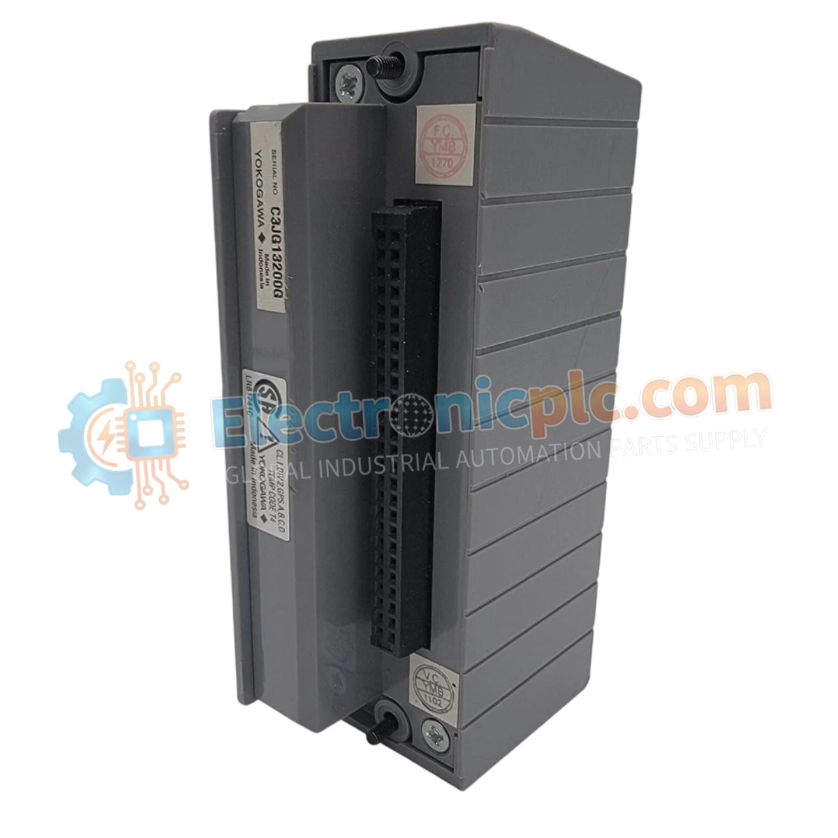
Configured for high-density field signal termination in DCS architectures, the Yokogawa ATB5S-00 (ATB5S-00 S2) Digital Input Terminal Block provides direct physical electrical execution for 32-point signal interfacing.
Availability: Low stock: 99 left
Reliable Worldwide Delivery
30-Day Money-Back Guarantee
Need more details? Read our fullShipping PolicyandRefund Policy.


Configured for high-density field signal termination in DCS architectures, the Yokogawa ATB5S-00 (ATB5S-00 S2) Digital Input Terminal Block provides direct physical electrical execution for 32-point signal interfacing.
| Parameter | Specification |
|---|---|
| Model | ATB5S-00 S2 |
| Brand | Yokogawa |
| Origin | Not Specified |
| Weight | 0.2 kg |
| Dimensions | 2.2 cm x 12.4 cm x 12.6 cm |
| Operating Temp | Not Specified |
| Power Consumption | Passive (N/A) |
| Capacity | 32 Digital Input Points |
The ATB5S-00 S2 utilizes a pressure clamp termination method to maintain contact integrity for digital signals routed to the ADV151 I/O modules. The unit acts as a physical bridge, ensuring channel-to-channel isolation consistency by minimizing cross-talk between high-density input loops. When configured with an integrated surge absorber, the block provides transient suppression, protecting the downstream input modules from voltage spikes originating in the field-level wiring.
Q: Can the ATB5S-00 S2 be used with input modules other than the ADV151?
A: The terminal block is specifically engineered for impedance matching and connector pinout alignment with the ADV151 module; usage with non-compatible hardware can lead to signal errors or physical damage to the module pins.
Q: How is the surge absorber functionality integrated into the block?
A: Depending on the specific suffix selection, the surge absorber is typically embedded within the PCB layer of the terminal block to provide a low-impedance path to ground for transient energy before it reaches the I/O interface.


