
My Cart
0 items
Genuine Automation Parts | Worldwide Express Delivery | 12-Month Warranty — [GET A QUOTE]

Configured for high-precision temperature and resistance acquisition, the YOKOGAWA ATSR3D-0 (ATSR3D-0 Analog RTD/POT Module) provides direct physical execution of analog signal conversion within control networks. The module serves as a...
Availability: In stock
Reliable Worldwide Delivery
30-Day Money-Back Guarantee
Need more details? Read our fullShipping PolicyandRefund Policy.
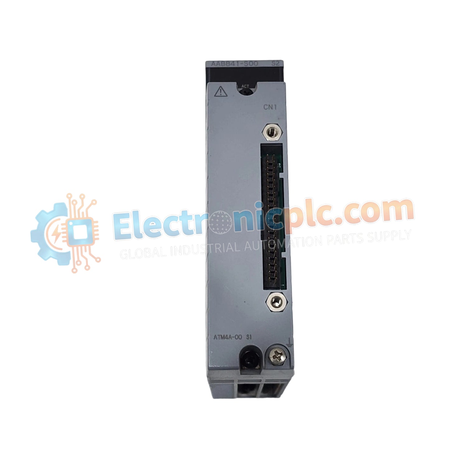

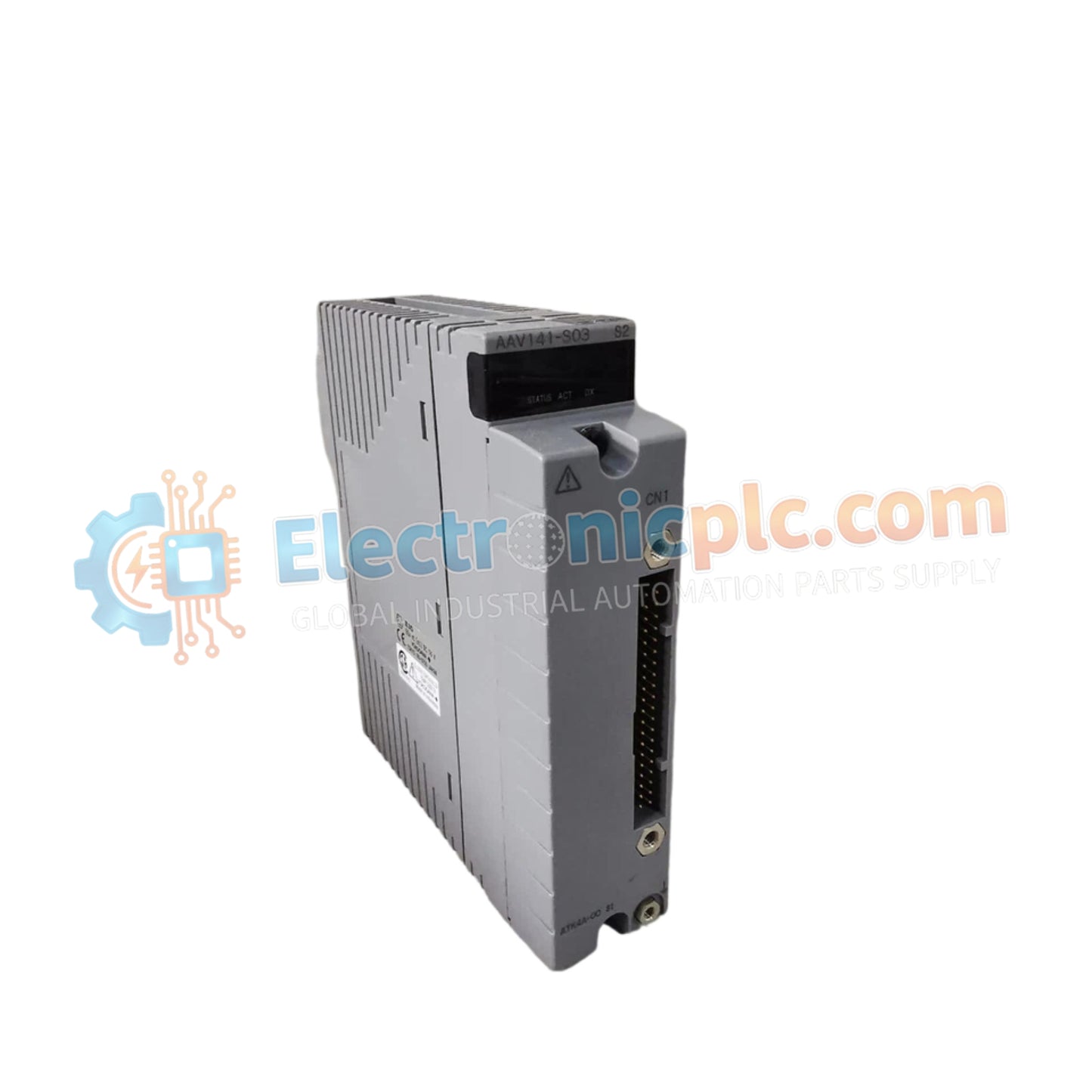
Configured for high-precision temperature and resistance acquisition, the YOKOGAWA ATSR3D-0 (ATSR3D-0 Analog RTD/POT Module) provides direct physical execution of analog signal conversion within control networks. The module serves as a primary interface for Resistance Temperature Detectors (RTDs) and potentiometers, facilitating dual-redundant analog signal output for critical process monitoring and control loops.
| Parameter | Specification |
|---|---|
| Model | ATSR3D-0 |
| Brand | YOKOGAWA |
| Origin | japan |
| Weight | 0.4kg |
| Dimensions | Compact industrial footprint |
| Operating Temp | Standard industrial range |
| Power Consumption | Subject to loop load |
| Input Type | RTD (Pt100, Pt500) / Potentiometer |
| Output Type | Dual-redundant linear analog |
The ATSR3D-0 architecture utilizes internal circuitry to ensure signal linearity between resistance inputs and the corresponding voltage outputs. While the module is optimized for RTD and potentiometer interfacing, it maintains consistent signal fidelity across both channels through channel-to-channel isolation techniques. This isolation prevents ground loops and electrical interference from influencing measurement accuracy in multi-sensor installations. The module design is calibrated to provide a stable 4-20 mA HART loop protocol compliant output, ensuring compatibility with standard DCS and PLC input cards without the requirement for dedicated cold junction compensation (CJC) circuits typically found in thermocouple modules.
Q: Can the ATSR3D-0 operate with a single output if the redundant channel fails?
A: Yes. The module is engineered for dual-redundant output execution; if a fault is detected in one output channel, the secondary channel maintains signal transmission to ensure the control system retains process visibility.
Q: Is this module field-configurable for different RTD types?
A: Yes. The module supports various RTD configurations; however, configuration parameters must be verified through the hardware interface or software settings to match the specific resistance-temperature curve of the connected sensor.


