My Cart
0 items
Genuine Automation Parts | Worldwide Express Delivery | 12-Month Warranty — [GET A QUOTE]

Configured for high-speed network communication within industrial control systems, the Yokogawa YCB141-M035 (YCB141-M035 Coaxial Bus Cable) provides direct physical signal transmission for V net, ER bus, ESB bus, and RIO...
Availability: In stock
Reliable Worldwide Delivery
30-Day Money-Back Guarantee
Need more details? Read our fullShipping PolicyandRefund Policy.
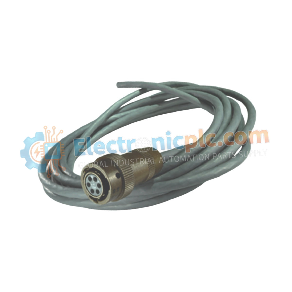


Configured for high-speed network communication within industrial control systems, the Yokogawa YCB141-M035 (YCB141-M035 Coaxial Bus Cable) provides direct physical signal transmission for V net, ER bus, ESB bus, and RIO bus platforms.
| Model | Component Description |
|---|---|
| YCB141 | Base Coaxial Bus Cable series (10BASE-2) |
| -M035 | Cable length configuration (35 meters) |
| Parameter | Specification |
|---|---|
| Model | YCB141-M035 |
| Brand | Yokogawa |
| Origin | japan |
| Weight | 0.85kg |
| Dimensions | 35 meters length |
| Operating Temp | -20 deg C to +70 deg C |
| Power Consumption | Passive component |
| Communication Standard | 10BASE-2 |
| Connector Type | Solderless lug with M4 screws |
| Minimum Bend Radius | 50 mm |
The YCB141-M035 is engineered to maintain low-latency data flow within Yokogawa CENTUM VP and ProSafe-RS architectures. The cable utilizes intrinsic safety (Ex i) barrier-compatible construction where required and provides DIN-rail mounting stability when used in conjunction with secondary conduit routing. The assembly offers surge voltage protection limits necessary for maintaining communication link stability in high-EMI industrial zones. By adhering to 10BASE-2 standards, the cable ensures protocol conversion latencies are kept within the precise millisecond tolerances required for deterministic V net and ER bus communication.
Q: Can the YCB141-M035 be used in high-EMI environments?
A: Yes. The coaxial design provides inherent electromagnetic shielding, and when properly terminated and grounded, it effectively rejects RFI/EMI common in process control cabinet environments.
Q: What is the risk of exceeding the 50 mm bending radius?
A: Exceeding this radius creates excessive mechanical stress on the dielectric layer and the center conductor. This causes characteristic impedance deviation, leading to signal reflections and potential data frame corruption on the bus network.


