My Cart
0 items
Genuine Automation Parts | Worldwide Express Delivery | 12-Month Warranty — [GET A QUOTE]

Configured for high-precision signal acquisition in process control platforms, the Yokogawa ADM11/CE1 (ADM11 Contact Input Module) provides direct physical/electrical execution of multi-format analog signal conversion across 8 single-ended or 4...
Availability: In stock
Reliable Worldwide Delivery
30-Day Money-Back Guarantee
Need more details? Read our fullShipping PolicyandRefund Policy.


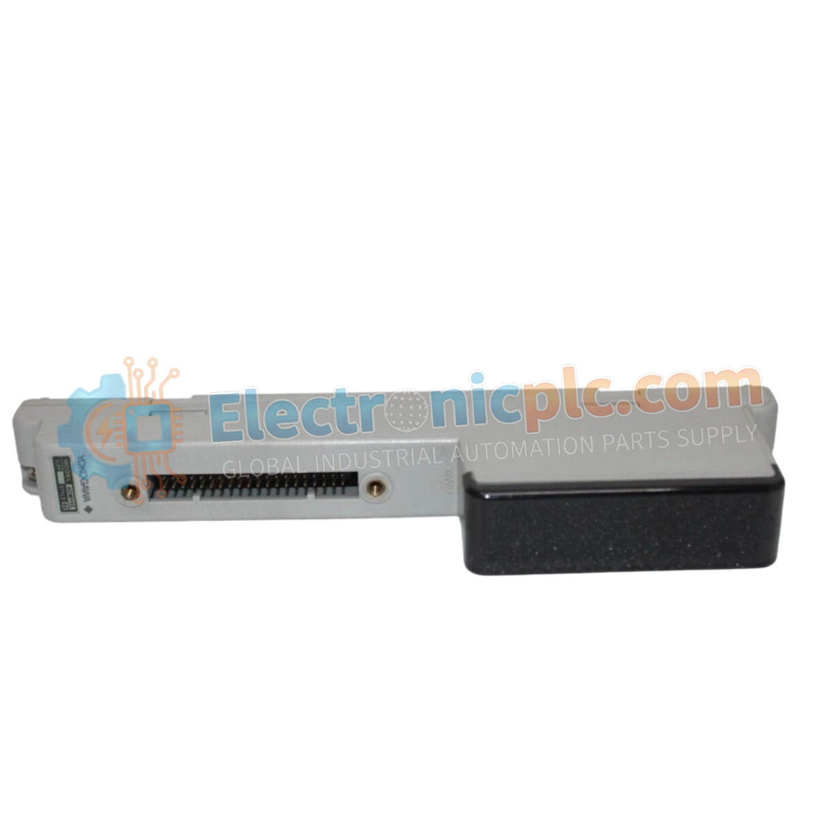
Configured for high-precision signal acquisition in process control platforms, the Yokogawa ADM11/CE1 (ADM11 Contact Input Module) provides direct physical/electrical execution of multi-format analog signal conversion across 8 single-ended or 4 differential input channels.
| Parameter | Specification |
|---|---|
| Model | ADM11/CE1 |
| Brand | Yokogawa |
| Origin | Japan |
| Weight | 0.5 kg |
| Dimensions | Standard DCS I/O module footprint |
| Operating Temp | -20 deg C to 60 deg C |
| Power Consumption | 24 VDC (+/- 10%) |
| Input Channels | 8 single-ended or 4 differential |
| Input Types | Voltage, current, thermocouple, RTD, resistance |
| Resolution | 16-bit |
| Accuracy | +/- 0.05% of reading +/- 5 uV |
| Conversion Speed | 10 ms/channel (max) |
The ADM11/CE1 provides robust signal processing through integrated channel-to-channel and channel-to-ground isolation. This design minimizes ground loops and cross-talk during the measurement of low-level signals such as thermocouple or RTD inputs. To maintain the rated 16-bit resolution and +/- 0.05% accuracy, the module employs high Common Mode Rejection (120 dB at 50/60 Hz) and Normal Mode Rejection (60 dB at 50/60 Hz) to filter line frequency interference. For high-precision temperature measurements, users must account for cold junction compensation (CJC) requirements and ensure that field wiring impedances remain within the specified range to preserve the integrity of the measurement loop.
Q: Can the input configuration be changed via software while the module is active?
A: No. Channel configuration (single-ended vs. differential) must be defined during the initial system commissioning and project file compilation. Changing input modes requires power cycling the module and updating the configuration database.
Q: Is this module capable of sustaining signal accuracy if the 24 VDC power supply fluctuates beyond 10%?
A: No. Operating the module outside the specified 24 VDC (+/- 10%) range can cause instability in the internal voltage references, leading to measurement drift that exceeds the defined +/- 0.05% accuracy limit.


