My Cart
0 items
Genuine Automation Parts | Worldwide Express Delivery | 12-Month Warranty — [GET A QUOTE]

The YOKOGAWA CP451-10 S2, also cataloged as the CP451-10 Processor Module, operates as a dedicated hardware component for centralized logic execution and data processing within...
Availability: Low stock: 99 left
Reliable Worldwide Delivery
30-Day Money-Back Guarantee
Need more details? Read our fullShipping PolicyandRefund Policy.


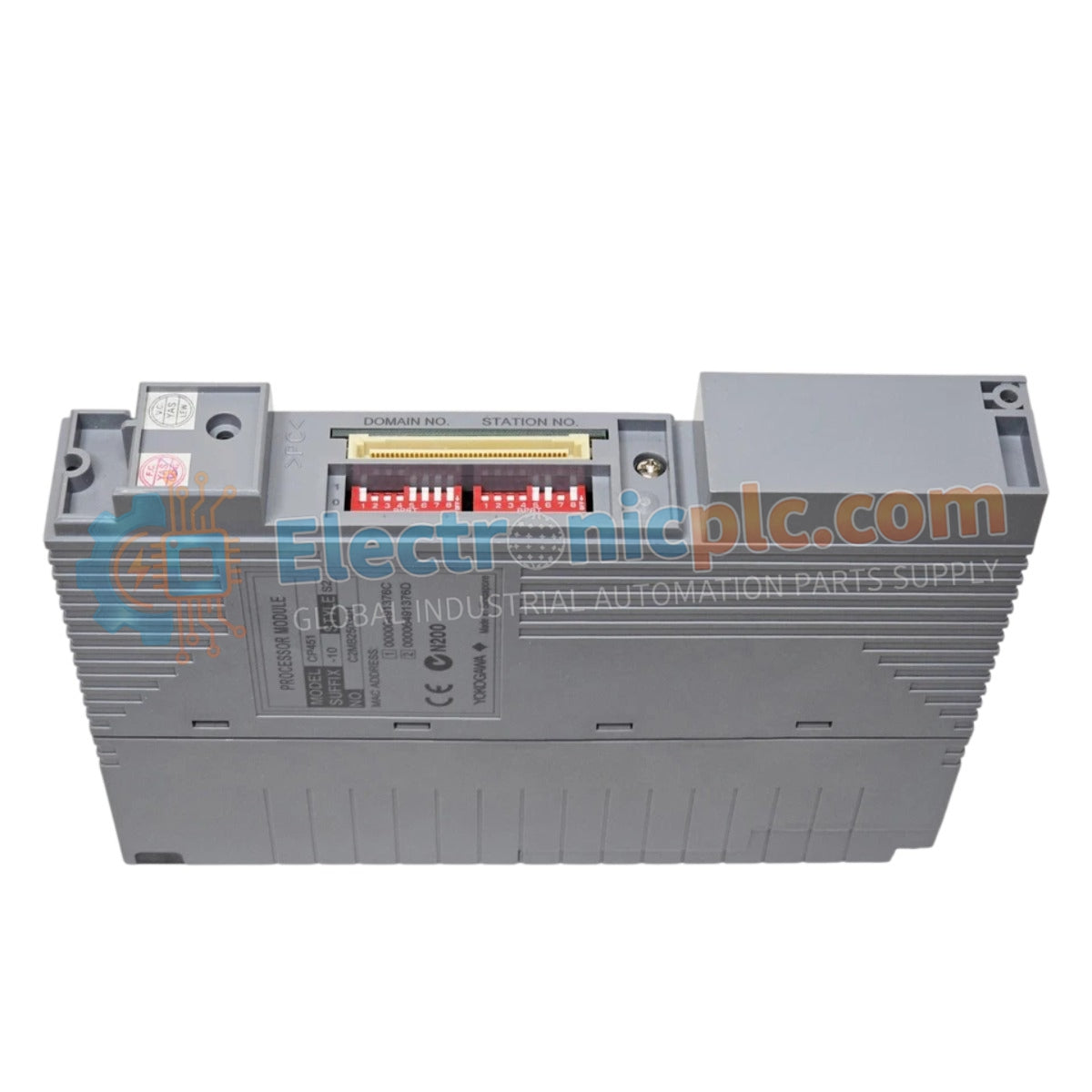
The YOKOGAWA CP451-10 S2, also cataloged as the CP451-10 Processor Module, operates as a dedicated hardware component for centralized logic execution and data processing within distributed control system platforms.
| Parameter | Specification |
| Model | CP451-10 S2 |
| Brand | YOKOGAWA |
| Origin | Japan |
| Weight | 0.74 kg |
| Dimensions | 3.2 cm x 14.8 cm x 20 cm |
| Operating Temp | Industrial environmental standard |
| Power Consumption | System backplane dependent |
| Processing Capacity | Real-time control execution |
The CP451-10 S2 is engineered to maintain high-fidelity data acquisition and regulatory loop stability. The module supports integration with standard 4-20 mA HART loop protocol architectures, ensuring consistent communication between field instrumentation and the DCS controller. To ensure signal fidelity across complex control architectures, the design incorporates channel-to-channel isolation, which mitigates ground loop interference and cross-channel electrical noise. This structural approach ensures that process variables are relayed to the central processor with the precision required for stable regulatory control in dynamic industrial environments.
Q: Does the CP451-10 S2 support redundant controller configurations?
A: Yes, this module supports redundant pairing. Ensure both primary and standby modules are synchronized with identical firmware and database versions to prevent switchover latency or control disruptions during failover.
Q: Can this processor module be hot-swapped while the field control unit is powered?
A: Hot-swapping is conditional upon the backplane revision and system status. Always verify that the module is in a non-primary state and that the system status permits removal before extraction to avoid unexpected I/O state changes.
Ensure the control cabinet power is fully isolated before installing or removing the module to prevent electrical faults on the backplane bus.
Align the module chassis with the rack guide rails and apply firm pressure to ensure the rear-mounted connectors fully engage with the backplane receptacle.
Secure the module using the integrated front-panel locking levers to maintain the necessary contact pressure and vibration resistance.
Ground the shield of all connected I/O cabling to the cabinet's potential equalization bus to minimize electromagnetic susceptibility and signal noise.
Conduct a visual inspection of the status indicators after system power-up to confirm the module has passed self-diagnostics and is active on the control network.


