
My Cart
0 items
Genuine Automation Parts | Worldwide Express Delivery | 12-Month Warranty — [GET A QUOTE]

The YOKOGAWA NFCP050, also cataloged as the NFCP050 CPU module, operates as a dedicated hardware component for localized process control and logic execution within FCN-RTU system architectures. This module provides high-speed central processing...
Availability: In stock
Reliable Worldwide Delivery
30-Day Money-Back Guarantee
Need more details? Read our fullShipping PolicyandRefund Policy.


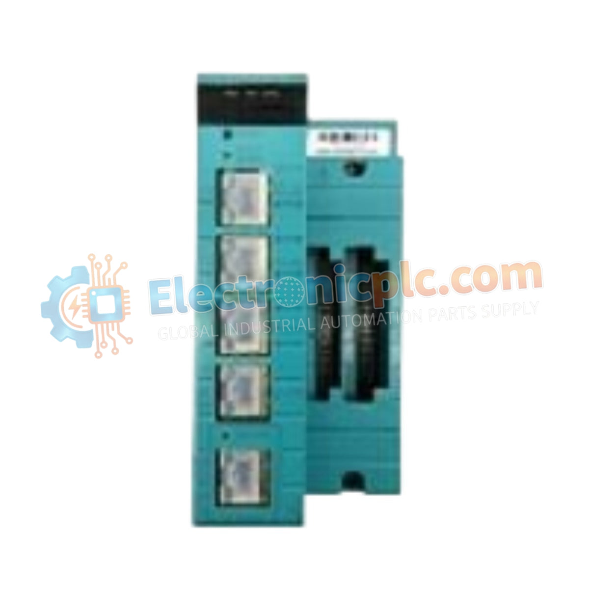
The YOKOGAWA NFCP050, also cataloged as the NFCP050 CPU module, operates as a dedicated hardware component for localized process control and logic execution within FCN-RTU system architectures. This module provides high-speed central processing and integrated signal conditioning for diverse field I/O requirements.
| Parameter | Specification |
| Model | NFCP050 |
| Brand | YOKOGAWA |
| Origin | JAPAN |
| Weight | 0.57 kg |
| Dimensions | 14.25 cm x 6.58 cm x 13 cm |
| Operating Temp | -20 deg C to 70 deg C |
| Power Consumption | 12 W typical |
| CPU | SH-4A (SH7730) 256 MHz |
| Memory | 128 MB on-board flash |
| I/O Capacity | 16 DI, 8 DO, 13 AI, 2 AO, 2 PI |
The NFCP050 CPU integrates directly with process control loops, supporting 4-20 mA HART loop protocol connectivity for standardized instrumentation. The design incorporates channel-to-channel isolation for critical analog inputs, ensuring precision signal processing in multi-loop instrumentation cabinets. The platform facilitates FOUNDATION Fieldbus communication, enabling seamless integration into established DCS environments while maintaining deterministic data exchange for real-time control applications.
Q: Does the NFCP050 support hot-swapping under normal operating conditions?
A: The NFCP050 module is not designed for hot-swapping. System power must be disconnected before module removal or installation to prevent backplane pin damage and potential corruption of the non-volatile memory.
Q: Are the RS-232 and RS-422/RS-485 communication ports electrically isolated?
A: No, the communication interfaces on the NFCP050 are non-isolated. Users must ensure proper signal ground referencing and implement external galvanic isolation barriers when connecting to field devices located in high-noise environments or across different potential zones.
Mount the module within the FCN-RTU base unit, ensuring the backplane connectors are correctly aligned and the retention latches are fully engaged to prevent intermittent signal loss.
Confirm that the input voltage supply matches the rated range for the FCN-RTU system; verify all wiring polarity for the 4-20 mA loop and digital input signals prior to energizing.
Utilize shielded twisted-pair cabling for all serial communication ports. The shield must be terminated at a single common ground point to minimize ground loop currents and EMI susceptibility.
Maintain a minimum clearance of 50 mm around the module ventilation apertures to prevent thermal buildup, ensuring operation stays within the specified ambient temperature limits.
Perform a cold boot sequence after initial power-up to verify firmware initialization and baseline diagnostic pass on the CPU and internal I/O circuits.


