
My Cart
0 items
Genuine Automation Parts | Worldwide Express Delivery | 12-Month Warranty — [GET A QUOTE]

The Yokogawa PSCAIAAN, also cataloged as the PSCAIAAN Critical Analog Input Module, operates as a dedicated hardware component for high-integrity signal acquisition within distributed control system platforms.
Availability: In stock
Reliable Worldwide Delivery
30-Day Money-Back Guarantee
Need more details? Read our fullShipping PolicyandRefund Policy.


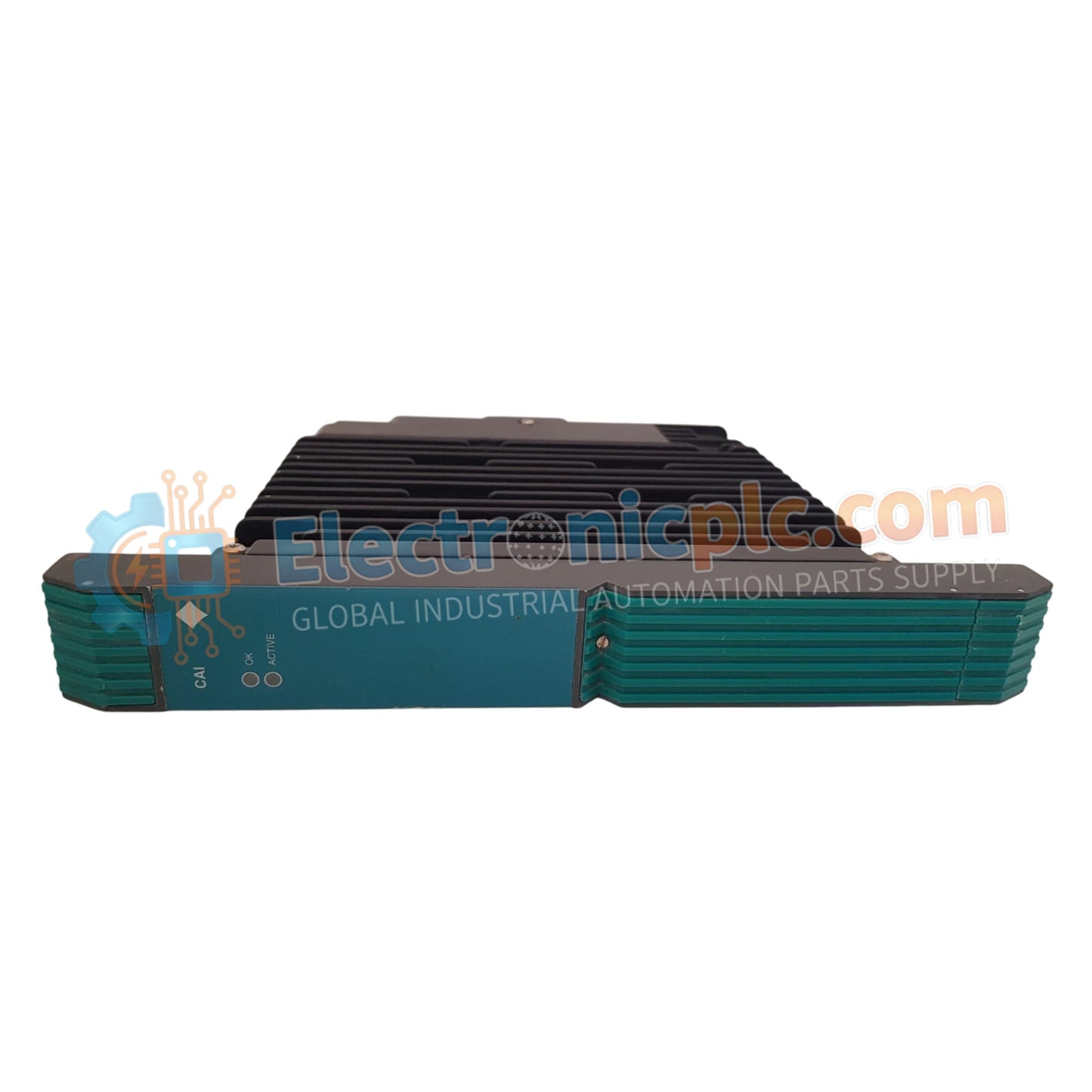
The Yokogawa PSCAIAAN, also cataloged as the PSCAIAAN Critical Analog Input Module, operates as a dedicated hardware component for high-integrity signal acquisition within distributed control system platforms.
| Parameter | Specification |
|---|---|
| Model | PSCAIAAN |
| Brand | Yokogawa |
| Origin | Japan |
| Weight | 1.88 kg |
| Dimensions | 4 cm x 25.7 cm x 30.6 cm |
| Operating Temp | 0 to 50 deg C |
| Power Consumption | 24 V DC nominal |
| Module Type | Critical Analog Input |
| Isolation | Galvanic channel-to-channel |
The PSCAIAAN utilizes the 4-20 mA HART loop protocol to facilitate precise analog input monitoring in safety-critical applications. The module architecture features advanced channel-to-channel isolation, which is necessary to prevent ground loops and common-mode interference in complex instrumentation networks. Furthermore, the unit supports cold junction compensation (CJC) for temperature-based input signals, ensuring measurement linearity and stability across the operational temperature spectrum. Proper termination of the loop is necessary to maintain signal accuracy and prevent impedance mismatches.
Q: Does the PSCAIAAN support redundant operation?
A: Yes. The module is engineered for integration into redundant I/O configurations where dual modules operate in parallel to ensure continuous data availability in the event of a single module fault.
Q: Is this module capable of performing on-line diagnostics?
A: Yes. The PSCAIAAN supports continuous diagnostic monitoring of loop continuity and signal range, providing real-time status feedback to the host controller regarding the health of the field instrument link.


