
My Cart
0 items
Genuine Automation Parts | Worldwide Express Delivery | 12-Month Warranty — [GET A QUOTE]

Configured for high-density signal processing in distributed automation platforms, the Yokogawa CSL/AMM12C (AMM12C Voltage Input Multiplexer Module) provides direct electrical execution for routing and multiplexing analog voltage inputs. This module...
Availability: Low stock: 50 left
Reliable Worldwide Delivery
30-Day Money-Back Guarantee
Need more details? Read our fullShipping PolicyandRefund Policy.


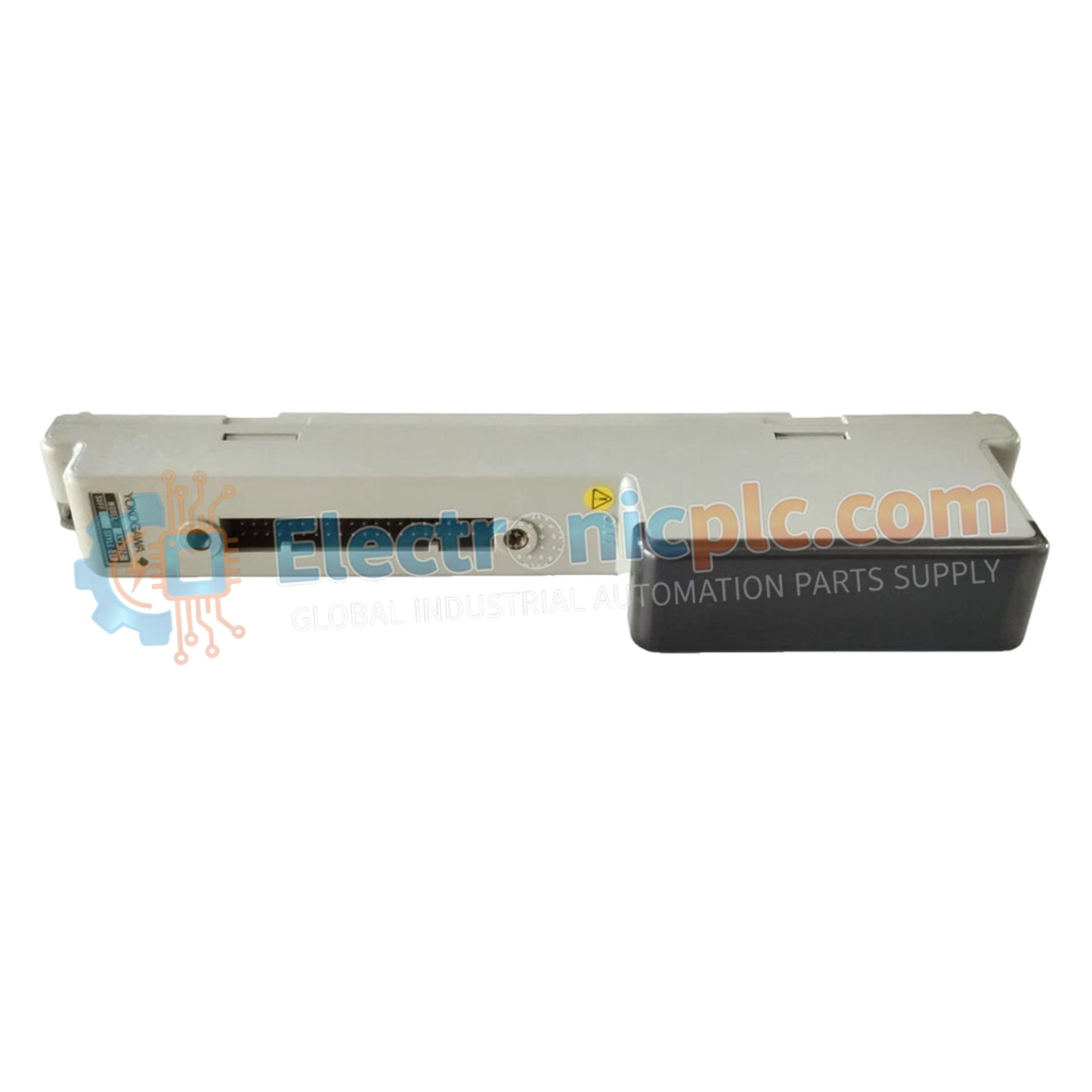
Configured for high-density signal processing in distributed automation platforms, the Yokogawa CSL/AMM12C (AMM12C Voltage Input Multiplexer Module) provides direct electrical execution for routing and multiplexing analog voltage inputs. This module manages 16 input channels, ensuring consistent data acquisition and scaling for process variables within industrial control architectures.
| Suffix Code | Specification |
|---|---|
| CSL/AMM12C | Base Voltage Input Multiplexer Module |
| Parameter | Specification |
|---|---|
| Model | CSL/AMM12C |
| Brand | Yokogawa |
| Origin | Japan |
| Weight | 0.3 kg |
| Dimensions | Standard I/O module footprint |
| Operating Temp | -10 deg C to +60 deg C |
| Power Consumption | Not specified |
| Input Points | 16 channels |
| Signal Interface | Terminal block connection |
| Redundancy | Dual-redundant configuration support |
The CSL/AMM12C architecture facilitates the consolidation of multiple voltage signal sources into a single processing path, optimizing input capacity within I/O cabinets. The module supports dual-redundant deployment, ensuring that signal acquisition paths remain active during primary controller switchover or communication bus faults. By maintaining strict electrical isolation between input terminals and the backplane, the unit effectively suppresses common-mode noise, maintaining the high-accuracy requirements necessary for precision voltage monitoring in process control environments.
Q: Does the AMM12C support hot-swapping while the process loop is active?
A: No, the module requires the removal of power from the backplane slot before extraction to prevent electrical transients from disrupting the redundant signal bus.
Q: Can this module be configured for mixed current and voltage inputs?
A: No, the CSL/AMM12C is specifically designed as a voltage input multiplexer; applying current inputs without appropriate external shunt resistors will result in inaccurate readings or hardware damage.


