My Cart
0 items
Genuine Automation Parts | Worldwide Express Delivery | 12-Month Warranty — [GET A QUOTE]

The YOKOGAWA CSL/PW301 Power Supply Module operates as a dedicated hardware component for power distribution within Yokogawa Centum VP DCS and process analyzer platforms. Configured to accept standardized AC inputs,...
Availability: Low stock: 99 left
Reliable Worldwide Delivery
30-Day Money-Back Guarantee
Need more details? Read our fullShipping PolicyandRefund Policy.


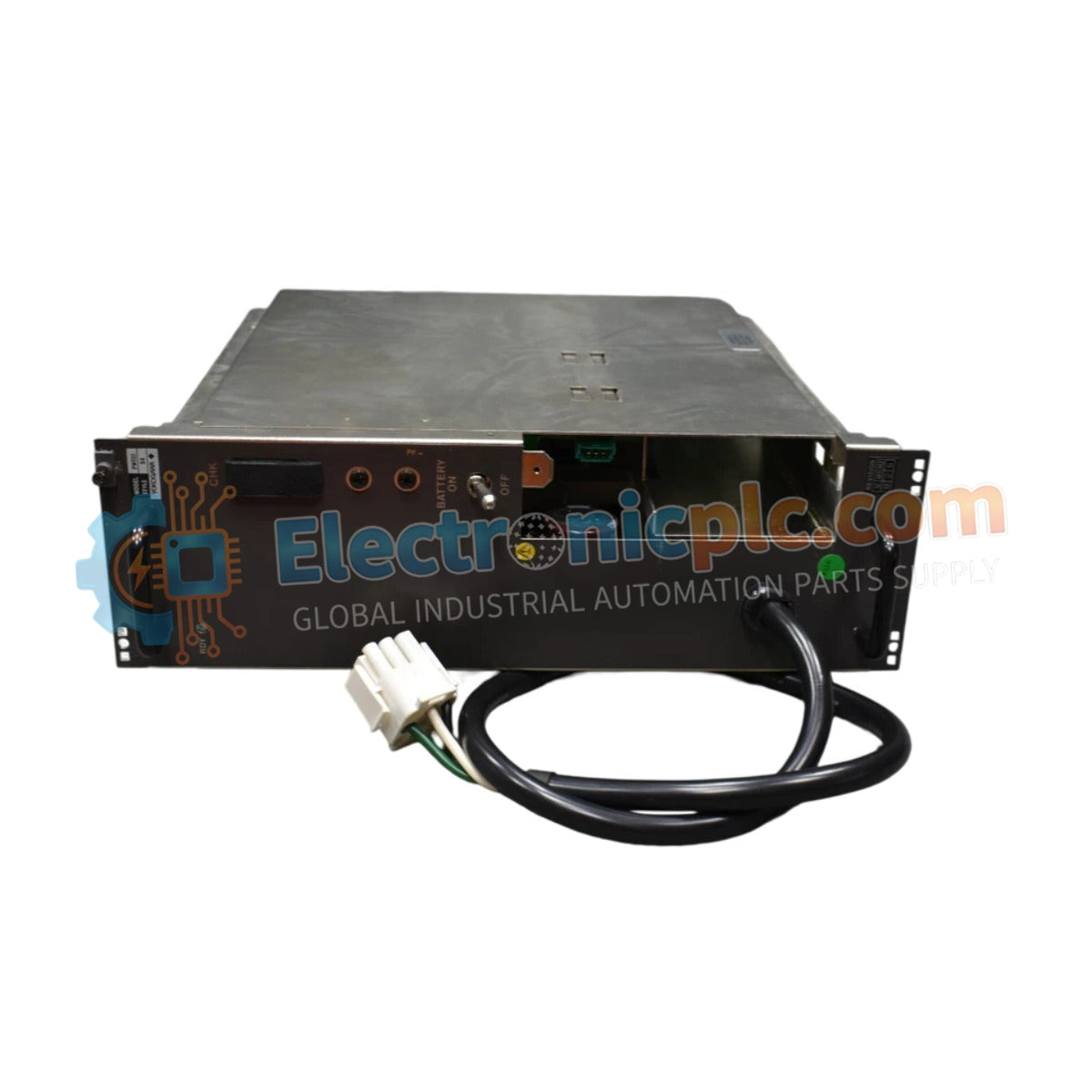
The YOKOGAWA CSL/PW301 Power Supply Module operates as a dedicated hardware component for power distribution within Yokogawa Centum VP DCS and process analyzer platforms. Configured to accept standardized AC inputs, this module regulates and stabilizes the electrical potential required for system backplane operations and associated control logic.
| Parameter | Specification |
|---|---|
| Model | CSL/PW301 |
| Brand | Yokogawa |
| Origin | Japan |
| Weight | 3.3 kg |
| Dimensions | 10.2 cm x 27.9 cm x 27.9 cm |
| Input Voltage | 100-120 VAC |
| Input Current | 6 A |
| Output Voltage | 5.1 VDC |
| Output Current | 15 A |
The CSL/PW301 facilitates stable voltage rails necessary for process control continuity. The unit incorporates channel-to-channel isolation to prevent ground loops and electrical noise injection into the control bus. Consistent voltage delivery is maintained across varying load conditions to ensure the integrity of the 4-20 mA HART loop protocol utilized by downstream instrumentation. Cold junction compensation (CJC) and precise thermal management are implemented within the power stage to maintain performance accuracy across the operational temperature range.
Q: Is the CSL/PW301 compatible with redundant power configurations?
A: Yes, the module is designed for load-sharing in redundant rack setups. Ensure that both modules are synchronized via the backplane and connected to separate power sources to prevent system-wide failure during an input line disturbance.
Q: What is the significance of the 5.1 VDC output?
A: The 5.1 VDC rail is utilized to power the logic-level circuitry and backplane communication processors. This specific voltage level is calibrated to minimize heat dissipation while maintaining signal integrity for high-speed digital communications across the DCS architecture.


