
My Cart
0 items
Genuine Automation Parts | Worldwide Express Delivery | 12-Month Warranty — [GET A QUOTE]

The Woodward 5466-1001, also cataloged as the 5466-1001 Power Supply Module, operates as a dedicated hardware component for stable power distribution and voltage conversion within MicroNet digital controller platforms. The...
Availability: Low stock: 6 left
Reliable Worldwide Delivery
30-Day Money-Back Guarantee
Need more details? Read our fullShipping PolicyandRefund Policy.


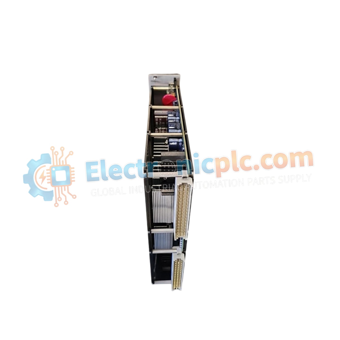
The Woodward 5466-1001, also cataloged as the 5466-1001 Power Supply Module, operates as a dedicated hardware component for stable power distribution and voltage conversion within MicroNet digital controller platforms. The module converts 110 VAC or 125 VDC main input lines into a regulated 24 VDC output at up to 16 A, supplying continuous operating power across the backplane chassis while maintaining network galvanic isolation up to 1000 Vrms.
| Parameter | Specification |
|---|---|
| Model | 5466-1001 |
| Brand | Woodward |
| Origin | USA |
| Weight | 4kg |
| Dimensions | 461 mm (H) x 265 mm (W) x 59 mm (D) |
| Operating Temp | -40 deg C to +105 deg C |
| Power Consumption | Converts to 24 VDC @ 16 A output (384 W max load) |
| Input Voltage | 110 VAC / 125 VDC |
| Output Voltage | 24 VDC |
| Max Output Current | 16 A |
| Maximum Stub Length | 300 mm |
| Network Isolation | 1000 Vrms (0-60 Hz) |
| Speed Sensing Range | 1 to 30 VAC |
The power supply chassis is engineered with optimized thermal heat sink dissipation profiles to withstand continuous operation in extreme environmental conditions. Utilizing heavy-duty aluminum conduction channels, the board dissipates heat generated by internal power electronics during 16 A load drops across an extended temperature window of -40 deg C to +105 deg C. This thermal management prevents voltage drift and thermal shutdown during peak demand cycles without requiring internal cooling fans.
Q: What input power sources can be wired to the primary input terminals?
A: The module accommodates both AC and DC industrial power feeds, operating on either 110 VAC or 125 VDC utility inputs without requiring physical jumper selection.
Q: How does the integrated network isolation protect backplane electronics?
A: The onboard isolation circuitry provides 1000 Vrms isolation across 0-60 Hz line frequencies, preventing high-voltage line surges and ground loops from transferring to sensitive controller backplane logic.
Q: What is the maximum permitted length for the secondary power stub connections?
A: Secondary power stub wiring must not exceed a maximum length of 300 mm to ensure low trace resistance and prevent voltage drops under high current loads.


