
My Cart
0 items
Genuine Automation Parts | Worldwide Express Delivery | 12-Month Warranty — [GET A QUOTE]

The Woodward DECS-100-B15, also cataloged as the DECS-100-B15 Automatic Voltage Regulator, operates as a dedicated hardware component for field excitation and voltage regulation within synchronous generator control systems. The microprocessor-based controller...
Availability: Low stock: 6 left
Reliable Worldwide Delivery
30-Day Money-Back Guarantee
Need more details? Read our fullShipping PolicyandRefund Policy.


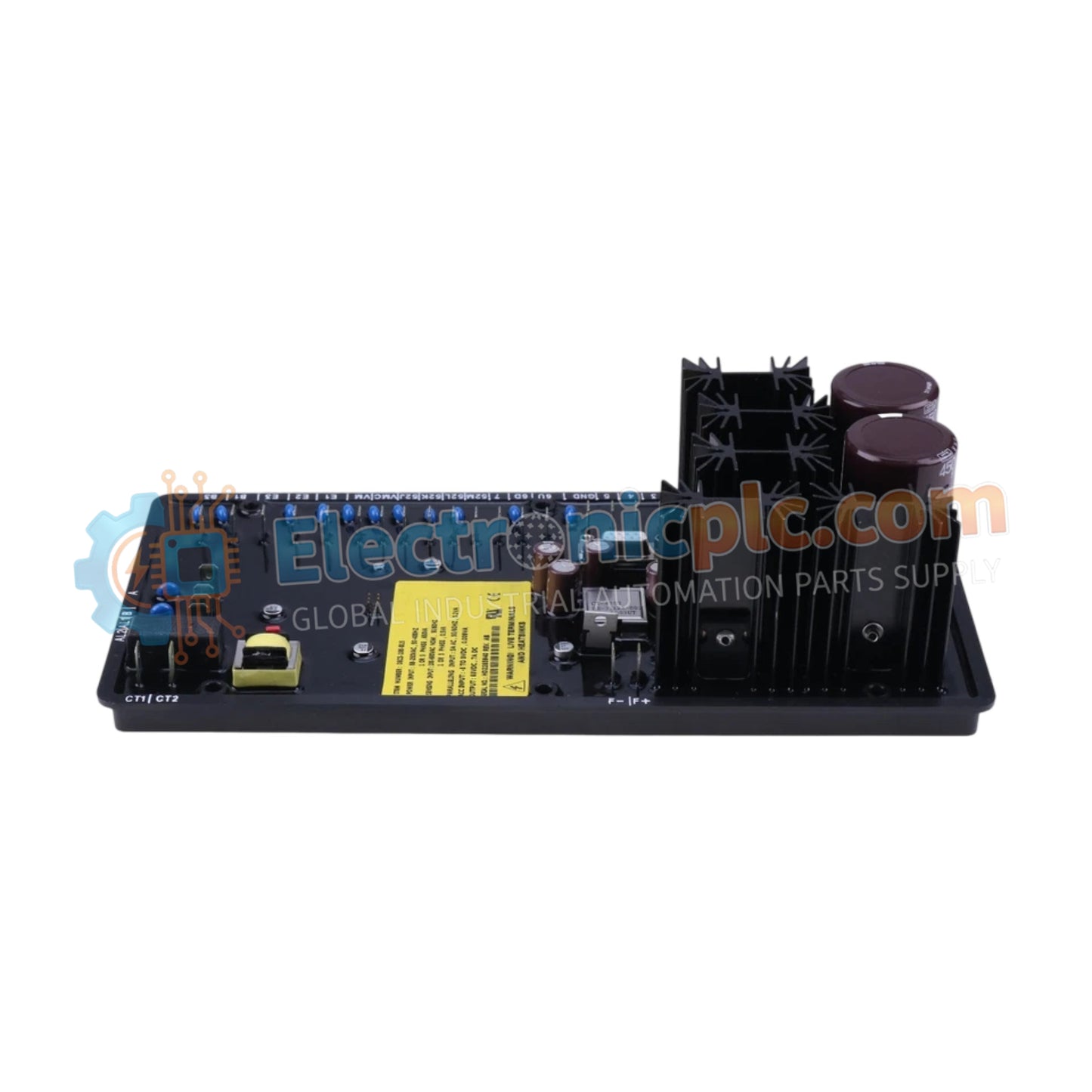
The Woodward DECS-100-B15, also cataloged as the DECS-100-B15 Automatic Voltage Regulator, operates as a dedicated hardware component for field excitation and voltage regulation within synchronous generator control systems. The microprocessor-based controller continuously samples generator terminal voltage and current inputs, providing continuous Pulse Width Modulation (PWM) field output up to 63 Vdc at 7 Adc to maintain targeted terminal parameters under fluctuating bus loads.
| Parameter | Specification |
|---|---|
| Model | DECS-100-B15 |
| Brand | Woodward |
| Origin | USA |
| Weight | Standard controller mass |
| Dimensions | Standard enclosure chassis |
| Operating Temp | Industrial rated operating spectrum |
| Power Consumption | Self-powered / auxiliary control power input |
| Voltage Regulation | 0.25% regulation accuracy |
| Output Ratings | 63 Vdc PWM output at 7 Adc continuous |
| Control Modes | AVR, Field Current (FCR), Power Factor (PF), VAR |
| Communication | PC software interface (BESTCOMS) |
The Woodward DECS-100-B15 utilizes onboard digital processing loops to calculate real-time excitation commands while maintaining deterministic communications over dedicated serial parameters. Serial interface compatibility allows parameter adjustments and diagnostic monitoring via BESTCOMS configuration software, maintaining firmware flash compatibility across varied generator control architectures and protection integration schemes.
Q: What control operating modes are available on the Woodward DECS-100-B15 unit?
A: The digital controller supports four software-selectable operating modes: Automatic Voltage Regulation (AVR), Field Current Regulation (FCR), Power Factor (PF) control, and Reactive Power (VAR) regulation.
Q: What are the output voltage and current drive limits of the PWM power stage?
A: The internal pulse-width modulated power output bridge delivers up to 63 Vdc at a continuous current rating of 7 Adc to the generator exciter field windings.
Q: What internal generator protection functions are incorporated into the device hardware?
A: The module incorporates built-in diagnostic and protective logic including overexcitation limiting, underexcitation limiting, loss of sensing voltage detection, and generator overvoltage tripping.


