
My Cart
0 items
Genuine Automation Parts | Worldwide Express Delivery | 12-Month Warranty — [GET A QUOTE]

Configured for high-speed discrete control in N-IO (Network I/O) platforms, the YOKOGAWA NFDV561-P50 (NFDV561 Digital Output Module) provides direct physical/electrical execution. This hardware component manages 16 sourcing digital output channels,...
Availability: In stock
Reliable Worldwide Delivery
30-Day Money-Back Guarantee
Need more details? Read our fullShipping PolicyandRefund Policy.


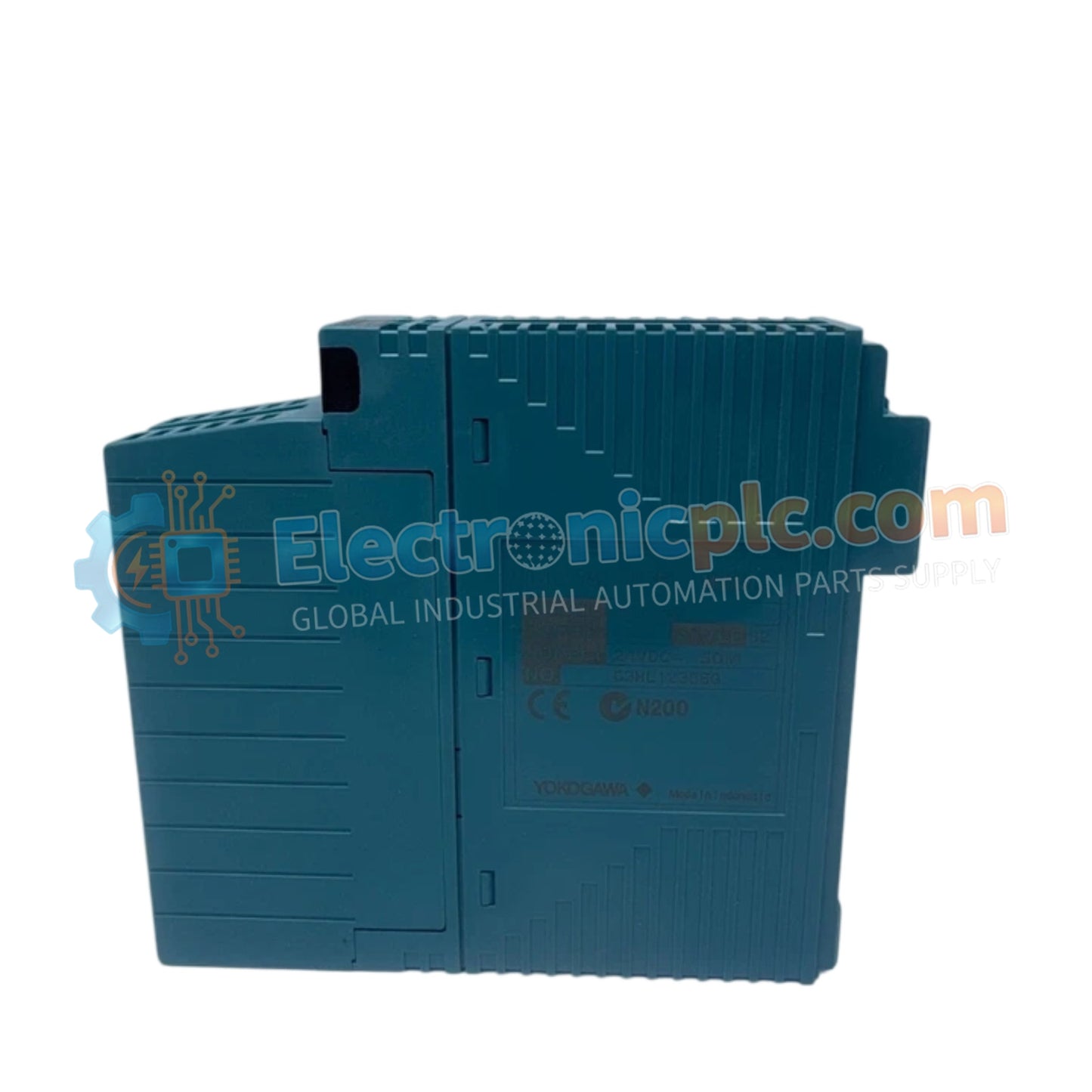
Configured for high-speed discrete control in N-IO (Network I/O) platforms, the YOKOGAWA NFDV561-P50 (NFDV561 Digital Output Module) provides direct physical/electrical execution. This hardware component manages 16 sourcing digital output channels, facilitating the deterministic activation of actuators, solenoids, and interposing relays within process control and manufacturing automation architectures.
| Parameter | Specification |
|---|---|
| Model | NFDV561-P50 |
| Brand | YOKOGAWA |
| Origin | JAPAN |
| Weight | 0.25 kg |
| Dimensions | Standard N-IO Module Form Factor |
| Operating Temp | -20 to 60 deg C |
| Power Consumption | 3.5 W (Max) |
| Output Channels | 16 |
| Output Type | Sourcing (Positive Logic) |
| Max Load Current | 0.5 A per channel (4 A per module) |
The NFDV561-P50 module is engineered for low-latency signal execution, achieving response times of 1 ms or less for both state transitions. The module architecture features 1500 V AC channel-to-bus galvanic isolation, preventing transient voltage spikes from the field-side output devices from impacting the N-IO node communication bus. Integrated diagnostics, including overcurrent protection and short-circuit detection, ensure the module maintains operational integrity when driving inductive loads.
Q: Does the 0.5 A per channel rating apply to all 16 channels simultaneously?
A: No, the total current draw per module is limited to 4 A. If all 16 channels are active, the load per channel must be derated to prevent thermal overload and trigger overcurrent protection.
Q: Is this module compatible with negative logic field devices?
A: The NFDV561-P50 is a sourcing (positive logic) module, meaning it provides 24 VDC output when enabled. For negative logic (sinking) applications, verify compatibility with the specific field device or utilize an interposing relay.


