
My Cart
0 items
Genuine Automation Parts | Worldwide Express Delivery | 12-Month Warranty — [GET A QUOTE]

Configured for digital pulse processing and rotational velocity monitoring in turbine governor systems, the Woodward 5462-408 (5462-408 Digital Speed Sensor Circuit Card) provides direct physical/electrical execution. This hardware component processes...
Availability: Low stock: 10 left
Reliable Worldwide Delivery
30-Day Money-Back Guarantee
Need more details? Read our fullShipping PolicyandRefund Policy.


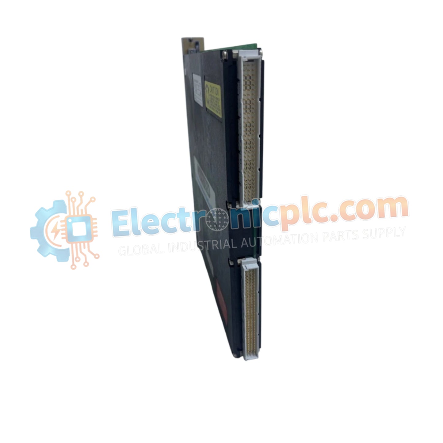
Configured for digital pulse processing and rotational velocity monitoring in turbine governor systems, the Woodward 5462-408 (5462-408 Digital Speed Sensor Circuit Card) provides direct physical/electrical execution. This hardware component processes frequency inputs from magnetic pickups or proximity sensors to deliver precise digital speed telemetry for prime mover control and overspeed protection loops.
| Parameter | Specification |
|---|---|
| Model | 5462-408 |
| Brand | Woodward |
| Origin | USA |
| Weight | 1.3 kg |
| Dimensions | 19.1 cm x 2.5 cm x 23.5 cm |
| Operating Temp | -20 deg C to +70 deg C |
| Power Consumption | 6 W max at 24 VDC |
| Input Signal | Frequency pulse from magnetic pickup or proximity sensor |
| Output Interface | Digital speed telemetry to system backplane bus |
The hardware utilizes high-speed digital counters and signal conditioning stages designed to minimize processing latency during actuator loop feedback response tracking across dynamic load shifts. Internal thermal heat sink dissipation profiles are structured to maintain uniform component junction temperatures within enclosed rack assemblies without forced-air ventilation. Advanced harmonic distortion suppression circuitry filters out high-frequency electromagnetic interference from adjacent high-voltage cabling on incoming sensor lines.
Q: What type of primary input signals are compatible with this speed sensor circuit card?
A: The card accepts alternating frequency pulses generated by magnetic pick-up units (MPU) or digital proximity probes as they detect passing gear teeth on a rotating shaft.
Q: Does the card require external power supply conditioning or does it run on standard backplane rails?
A: It operates on standard regulated DC supply rails provided directly through the control system rack backplane bus.


