Skip to product information
1 of 3

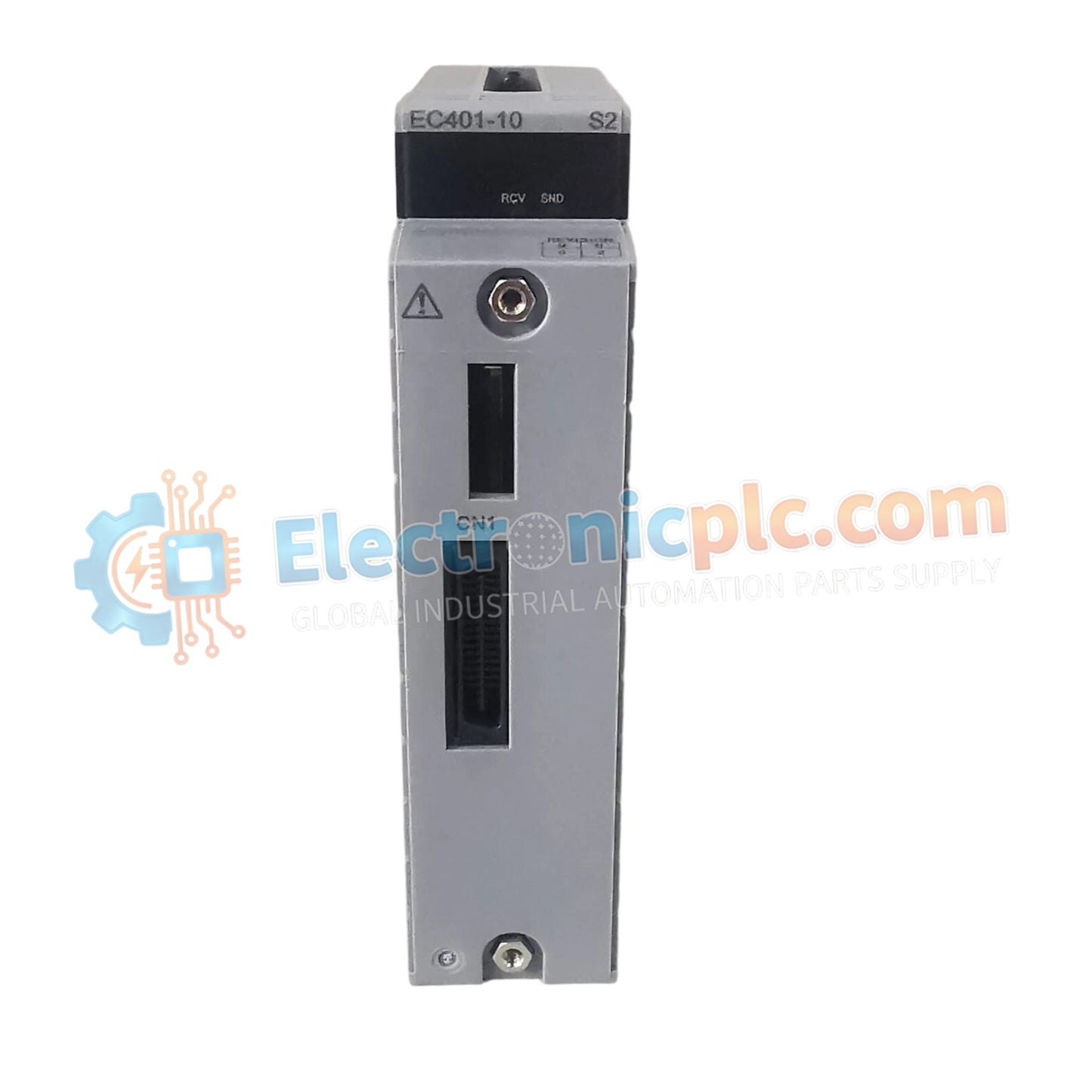
EC401-10 S2 Bus Coupler Module Yokogawa

EC401-10 S2 Bus Coupler Module Yokogawa

Configured for multi-protocol communication and bus coupling across industrial control networks, the Yokogawa EC401-10 S2 (EC401-10 S2 Bus Coupler Module) provides direct physical/electrical execution.

Suffix Breakdown & Model Matrix

    ...
17 people are viewing this right now

AvailabilityLow stock: 50 left

SKU: EC401-10-S2
Vendor: Yokogawa
Related Series:

Shipping & Returns

Reliable Worldwide Delivery

  • Carriers: Shipped via DHL, FedEx, UPS, or USPS.
  • Dispatch: Orders processed in 1-2 business days and dispatched within 3-5 business days.
  • Tracking: Full tracking details provided via email upon shipment.

30-Day Money-Back Guarantee

  • Guarantee: 30-day return window for in-stock, factory-sealed products.
  • Condition: Items must be unopened, unused, and in original packaging.
  • Authenticity: We guarantee 100% original and authentic hardware.

Need more details? Read our fullShipping PolicyandRefund Policy.

Authenticity & Warranty

  • Genuine Guarantee: We supply only 100% original, brand-new, and factory-sealed industrial automation parts.
  • Full Coverage: Every component is backed by a 12-month comprehensive warranty from the date of purchase.
  • Traceability: All products come with original factory documentation and accessories for full industrial compliance.

Technical Support & Sourcing

  • Expert Assistance: Our technical team provides free consultation to help you verify compatibility for DCS and PLC systems.
  • Rare Part Sourcing: Specializing in obsolete and hard-to-find components from Allen-Bradley, Siemens, ABB, HIMA, and more.
  • Bulk Inquiries: Contact us at pambo@5gplc.com for volume pricing or customized project quotes.
View full product details

Configured for multi-protocol communication and bus coupling across industrial control networks, the Yokogawa EC401-10 S2 (EC401-10 S2 Bus Coupler Module) provides direct physical/electrical execution.

Suffix Breakdown & Model Matrix

  • EC401: Base model designation for the bus coupler module architecture supporting serial communications.
  • -10: Version specifier indicating standard channel and protocol handling capabilities.
  • S2: Revision suffix indicating specific hardware build standards and environmental grading for industrial applications.

Hardware Specifications

Parameter Specification
Model EC401-10 S2
Brand Yokogawa
Origin Japan
Weight 0.3kg
Dimensions Standard DIN rail or rack mount footprint
Operating Temp 0 to 60 deg C (32 to 140 deg F)
Power Consumption Standard internal power rails
Channels & Interfaces 1 channel supporting RS-232, RS-422, and RS-485 serial interfaces
Baud Rate & Framing Up to 115200 bps; data bits 5 to 8; stop bits 1 or 2; parity none, odd, even
Protocols Modbus, ASCII, DNP3, PROFIBUS

Channel-to-Channel Isolation and Serial Communication

The module incorporates robust galvanic isolation across its serial communication ports, protecting internal processing logic from ground potential differences and electrical transients across field lines. Configurable support for RS-232, RS-422, and RS-485 interfaces ensures deterministic multi-protocol conversion and transparent data transfer for Modbus, ASCII, DNP3, and PROFIBUS frameworks.

Frequently Asked Questions

Q: Does the EC401-10 S2 module support online configuration changes without halting the host controller?

A: Serial communication parameters and protocol selections typically require a configuration reload or reset to initialize new settings properly.

Q: How are serial interface types selected for physical wiring connections?

A: Physical layer selection between RS-232, RS-422, and RS-485 is handled via module configuration settings and dedicated terminal connections.

Field Installation Guidelines

  • Mount the module securely onto a standard DIN rail or panel enclosure, ensuring sufficient clearance for thermal dissipation within the 0 to 60 deg C operating range.
  • Terminate serial communication cables onto the appropriate interface terminals, maintaining proper shielding and single-point grounding to prevent electromagnetic interference.
  • Verify correct power and signal wiring polarity before energizing the system.