My Cart
0 items
Genuine Automation Parts | Worldwide Express Delivery | 12-Month Warranty — [GET A QUOTE]

Engineered for high-integrity data orchestration within Yokogawa distributed control architectures, the YOKOGAWA EC401-10 S2 (EC401-10 S2) serves as a critical interface for the Extended Synchronous Bus (ESB). This bus coupler...
Availability: Low stock: 99 left
Reliable Worldwide Delivery
30-Day Money-Back Guarantee
Need more details? Read our fullShipping PolicyandRefund Policy.


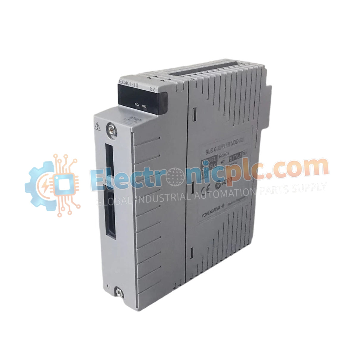
Engineered for high-integrity data orchestration within Yokogawa distributed control architectures, the YOKOGAWA EC401-10 S2 (EC401-10 S2) serves as a critical interface for the Extended Synchronous Bus (ESB). This bus coupler module facilitates deterministic communication between Field Control Units (FCUs) and associated I/O node units, ensuring stable and reliable data exchange in demanding industrial automation environments.
| Parameter | Specification |
|---|---|
| Model | EC401-10 S2 |
| Brand | Yokogawa |
| Weight | 0.3 kg |
| Dimensions | 102 mm x 60 mm x 18 mm |
| Origin | Japan |
| Function | ESB Bus coupling and signal synchronization |
| Compatibility | CENTUM series / FIO systems |
The EC401-10 S2 acts as the primary physical bridge for the ESB network. By managing signal distribution between the controller and remote I/O nodes, it minimizes data latency and packet loss. This hardware is essential for maintaining the real-time requirements of process control loops, ensuring that sensor data and command signals are synchronized across the entire DCS architecture.
Q: What are the primary differences between the EC401-10 and other EC series modules?
A: Variations in the suffix codes, such as the -10 S2, typically reflect differences in board-level firmware or component revisions intended for specific system architectures or regional standards. Always verify the part number against your existing control unit's documentation to ensure hardware compatibility.
Q: Is the module hot-swappable?
A: While the module is designed for modularity, refer to the specific Yokogawa system maintenance manual for your controller generation. Generally, power isolation is recommended prior to module removal to protect backplane logic.


