My Cart
0 items
Genuine Automation Parts | Worldwide Express Delivery | 12-Month Warranty — [GET A QUOTE]

Configured for high-speed data transmission between control stations and node units, the YOKOGAWA EC401-50 (EC401 ESB Bus Coupler Module) provides direct physical and electrical execution of ESB bus signal coupling...
Availability: Low stock: 99 left
Reliable Worldwide Delivery
30-Day Money-Back Guarantee
Need more details? Read our fullShipping PolicyandRefund Policy.


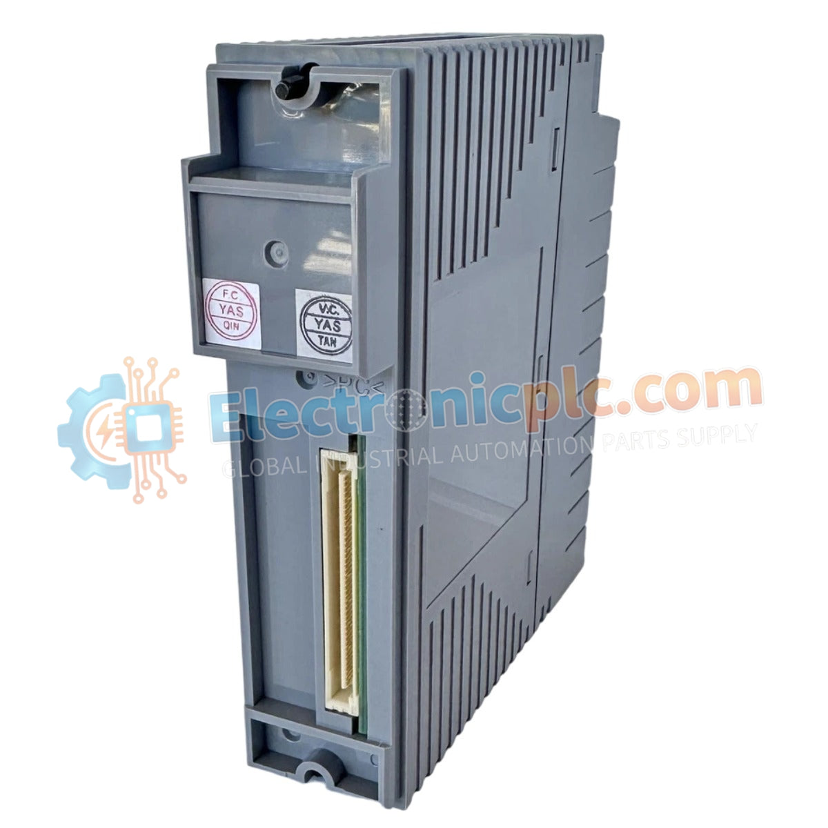
Configured for high-speed data transmission between control stations and node units, the YOKOGAWA EC401-50 (EC401 ESB Bus Coupler Module) provides direct physical and electrical execution of ESB bus signal coupling within CENTUM VP control systems.
| Parameter | Specification |
|---|---|
| Model | EC401-50 |
| Brand | YOKOGAWA |
| Origin | Japan |
| Weight | 0.4 kg |
| Dimensions | 2.2 x 12.4 x 12.6 cm |
| Operating Temp | Standard industrial range |
| Power Consumption | Subject to backplane supply |
| Bus Interface | ESB Bus |
| Mounting Type | Rack mount |
The EC401-50 module functions as a specialized interface that manages the synchronization of data packets between the Field Control Unit (FCU) and remote I/O nodes. The internal architecture facilitates galvanic isolation, protecting the system bus from electrical transients originating in the field-side cabling. By ensuring precise impedance matching across the ESB bus, the module prevents signal reflection and minimizes communication jitter. The unit is optimized to maintain the deterministic timing required for time-critical process data, ensuring that I/O status updates and control output commands are processed with high throughput across the network infrastructure.
Q: Does the EC401-50 support online replacement (hot-swap)?
A: No. This module does not support hot-swapping. The control station power must be fully de-energized before removing or installing the module to prevent electrical damage to the backplane connectors.
Q: Is the EC401-50 interchangeable with other ESB bus coupler models?
A: Compatibility depends on the specific hardware revision and system configuration. Always verify that the model number and suffix code match the existing installation requirements before replacement.


