
My Cart
0 items
Genuine Automation Parts | Worldwide Express Delivery | 12-Month Warranty — [GET A QUOTE]

Configured for high-speed data transmission in CENTUM distributed control systems, the YOKOGAWA EC401-51 S2 (EC401 ESB Bus Coupler Module) provides direct physical/electrical execution of the Extended-mode Synchronous Bus (ESB) communication...
Availability: Low stock: 50 left
Reliable Worldwide Delivery
30-Day Money-Back Guarantee
Need more details? Read our fullShipping PolicyandRefund Policy.


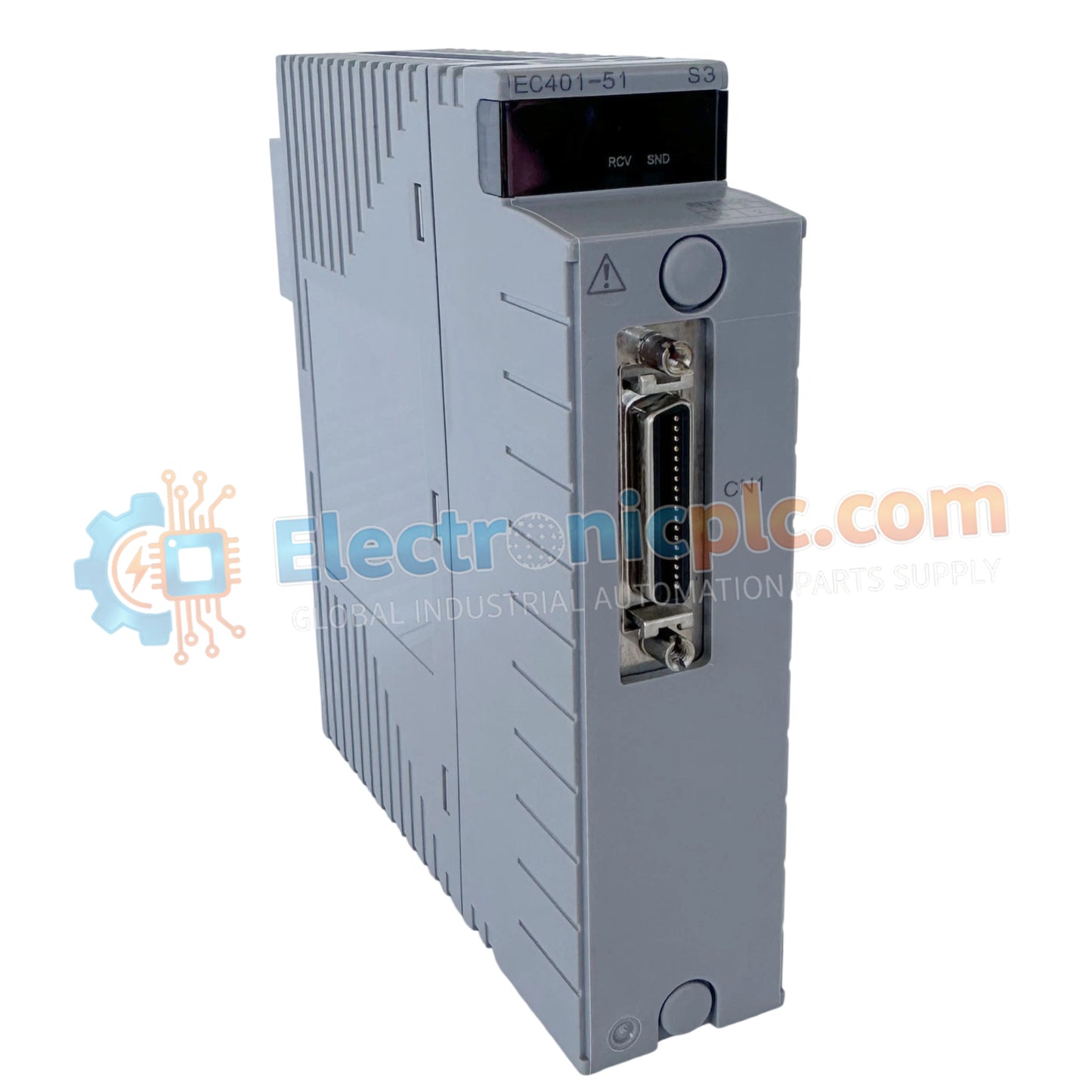
Configured for high-speed data transmission in CENTUM distributed control systems, the YOKOGAWA EC401-51 S2 (EC401 ESB Bus Coupler Module) provides direct physical/electrical execution of the Extended-mode Synchronous Bus (ESB) communication interface.
| Parameter | Specification |
|---|---|
| Model | EC401-51 S2 |
| Brand | YOKOGAWA |
| Origin | Japan |
| Weight | 0.3 kg |
| Dimensions | 22 mm x 124 mm x 126 mm |
| Operating Temp | Not specified |
| Power Consumption | Not specified |
| Bus Interface | ESB Bus (Extended Synchronous Bus) |
The EC401-51 S2 module facilitates system scalability by linking field control units (FCU) to remote I/O nodes via the ESB bus. The architecture supports deterministic data polling, ensuring that I/O scan intervals remain synchronized across the distributed network. Each module incorporates channel-to-channel isolation on the bus interface to maintain signal integrity and prevent noise propagation between the control station backplane and the remote node interface cables during high-frequency communication cycles.
Q: Is this module capable of supporting hot-swapping during active system operation?
A: No, the EC401-51 S2 is not designed for hot-swapping. The control station power must be isolated, and the bus communication stopped, before removing or installing the module to prevent electrical damage to the ESB bus backplane pins.
Q: What are the cable distance limitations for the ESB bus interface?
A: The ESB bus length is governed by the total latency constraints of the distributed control system. Refer to the specific system cabinet wiring guide to ensure total cable length and termination resistance are within the manufacturer’s specified parameters for stable communication.


