
My Cart
0 items
Genuine Automation Parts | Worldwide Express Delivery | 12-Month Warranty — [GET A QUOTE]

The YOKOGAWA F3AD08-5V (F3AD08 Analog Input Module) operates as a dedicated hardware component for high-density signal acquisition within FA-M3 Range-free Multi-controller PLC platforms. This module provides eight differential input channels designed for direct...
Availability: In stock
Reliable Worldwide Delivery
30-Day Money-Back Guarantee
Need more details? Read our fullShipping PolicyandRefund Policy.


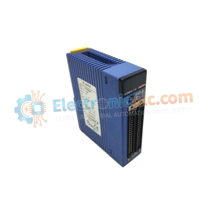
The YOKOGAWA F3AD08-5V (F3AD08 Analog Input Module) operates as a dedicated hardware component for high-density signal acquisition within FA-M3 Range-free Multi-controller PLC platforms. This module provides eight differential input channels designed for direct electrical execution of voltage and current monitoring tasks.
The F3AD08-5V is designated by the following configuration attributes:
F3: Series prefix denoting compatibility with the Yokogawa FA-M3 backplane architecture.
AD: Analog-to-digital input function.
08: Eight differential input channel capacity.
5V: 5 VDC nominal backplane power supply operation.
| Parameter | Specification |
| Model | F3AD08-5V |
| Brand | YOKOGAWA |
| Origin | Singapore |
| Weight | 0.2 kg |
| Dimensions | 28.9 mm x 100 mm x 106.1 mm |
| Operating Temp | 0 deg C to 55 deg C |
| Power Consumption | 210 mA at 5 V DC |
| Input Channels | 8 Differential |
| Input Impedance | >= 1 MOhm |
The F3AD08-5V supports high-speed backplane bus communication velocity, allowing the FA-M3 processor to perform rapid data acquisition cycles. Integrated signal processing features, including first-order lag filtering and moving average algorithms, are performed on-board, minimizing the load on the main CPU. The module ensures deterministic data exchange, supporting system-wide I/O density scaling while maintaining ±0.2% accuracy under standard operating conditions.
Q: Is the F3AD08-5V module capable of hot-swapping?
A: No, the module does not support hot-swapping. The power supply to the backplane rack must be disconnected before installation or removal to prevent potential damage to the internal logic or backplane connectors.
Q: How is field noise managed for the input channels?
A: The module supports configurable software-based filtering, specifically first-order lag filters and moving average processing. Additionally, the differential input architecture provides inherent common-mode noise rejection.
Mount the module into the designated slot of the FA-M3 base unit. Ensure the rear connectors are aligned correctly and the module is fully seated before tightening the retention screws.
Terminate field wiring using the 18-point detachable terminal block. Use M3.5 crimp-type lugs to ensure secure connections and prevent vibration-induced loosening.
Observe common-mode voltage limits (±1 V DC for the 10 V range; ±6 V DC for the 5 V / 20 mA range) to prevent measurement errors or damage to the input stage.
Utilize shielded twisted-pair cabling for all analog signals. Terminate shields to the cabinet ground at a single location to eliminate ground loops.
Perform a diagnostic loop check using the PLC configuration software to verify channel addressing and offset/scaling values after initial power-on.


