
My Cart
0 items
Genuine Automation Parts | Worldwide Express Delivery | 12-Month Warranty — [GET A QUOTE]

The YOKOGAWA F3DA08-5N (F3DA08-5N Analog Output Module) serves as the primary I/O module utilized to execute high-density signal conversion across FA-M3 (PLC) controller platforms. The module provides direct electrical execution...
Availability: In stock
Reliable Worldwide Delivery
30-Day Money-Back Guarantee
Need more details? Read our fullShipping PolicyandRefund Policy.


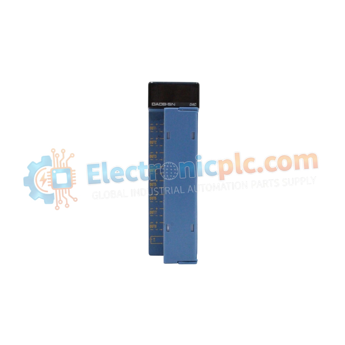
The YOKOGAWA F3DA08-5N (F3DA08-5N Analog Output Module) serves as the primary I/O module utilized to execute high-density signal conversion across FA-M3 (PLC) controller platforms. The module provides direct electrical execution of -10 to 10 VDC output signals across 8 independent channels, functioning as an interface component for actuator control and process positioning.
| Parameter | Specification |
|---|---|
| Model | F3DA08-5N |
| Brand | YOKOGAWA |
| Origin | Japan |
| Weight | 0.3kg |
| Dimensions | Standard PLC module footprint |
| Operating Temp | 0 to 55 deg C |
| Power Consumption | 5 VDC / 24 VDC internal supply |
| Channel Count | 8 channels |
| Output Range | -10 to 10 VDC |
The F3DA08-5N is engineered for high-density I/O scaling within FA-M3 modular rack systems. The module facilitates rapid backplane bus communication, allowing the host CPU to refresh all 8 output channels within a single scan cycle. This deterministic performance is supported by firmware flash compatibility, enabling the module to interface with various processor revisions without requiring hardware replacement. The output circuitry is designed to provide high-resolution voltage sourcing, maintaining signal stability even under varying capacitive loads typical of long-distance actuator signaling.
Q: Does the F3DA08-5N support hot-swapping within the PLC rack?
A: No. The module is not designed for hot-swapping. The rack power supply must be disabled before inserting or extracting the module to avoid damage to the backplane communication pins.
Q: Can the channels be configured for current output instead of voltage?
A: No. The F3DA08-5N is a dedicated voltage output module providing -10 to 10 VDC. Attempting to draw current loads beyond the specified limits or applying external voltages to the outputs will result in permanent damage to the channel drivers.


