My Cart
0 items
Genuine Automation Parts | Worldwide Express Delivery | 12-Month Warranty — [GET A QUOTE]

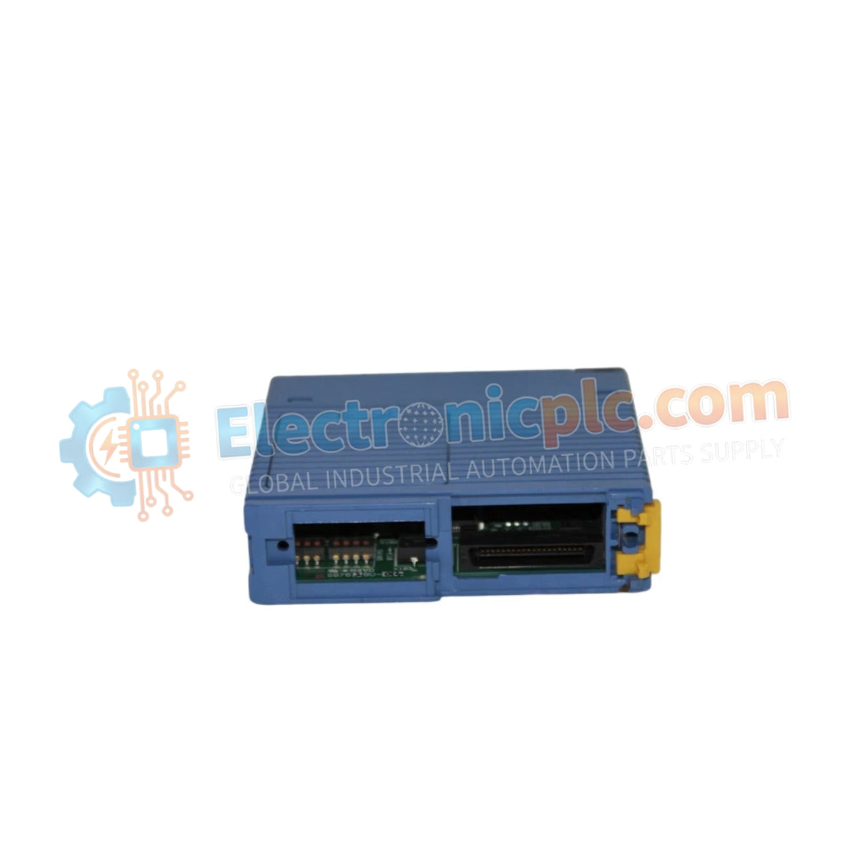
Configured for high-speed signal distribution in FA-M3 networks, the Yokogawa F3LR02-0N (F3LR02 Fiber-Optic FA-Bus Module) provides direct physical and electrical execution of long-distance data transmission using optical protocols.
Availability: Low stock: 99 left
Reliable Worldwide Delivery
30-Day Money-Back Guarantee
Need more details? Read our fullShipping PolicyandRefund Policy.


Configured for high-speed signal distribution in FA-M3 networks, the Yokogawa F3LR02-0N (F3LR02 Fiber-Optic FA-Bus Module) provides direct physical and electrical execution of long-distance data transmission using optical protocols.
| Parameter | Specification |
|---|---|
| Model | F3LR02-0N |
| Brand | Yokogawa |
| Origin | Japan |
| Weight | 0.2 kg |
| Dimensions | 2.89 cm x 10.0 cm x 8.32 cm |
| Operating Temp | 0 to 55 deg C |
| Power Consumption | 2.3 W (typical) |
| Transmission Speed | 10 Mbps |
The module architecture manages backplane bus communication velocity to support deterministic data exchange across distributed controller stations. By utilizing a 2-port send/receive optical interface, the F3LR02-0N facilitates I/O density scaling via daisy-chain configurations, allowing for up to 32 stations per system network. The fiber-optic transmission medium inherently provides total immunity to electromagnetic interference, ensuring that data packets remain free from corruption even when routed near high-voltage industrial equipment or large-scale variable frequency drives.
Q: Does the F3LR02-0N require specialized fiber-optic cleaning tools during field installation? A: Yes. All fiber connectors must be cleaned using lint-free wipes and isopropyl alcohol prior to insertion to prevent attenuation caused by dust or microscopic debris at the optical interface.
Q: Can the maximum transmission distance be extended beyond 500 meters? A: No. Exceeding 500 meters results in unacceptable optical signal attenuation and frame synchronization errors. Any extension requirements necessitate the use of intermediate optical repeaters outside of this specific module's architecture.


