My Cart
0 items
Genuine Automation Parts | Worldwide Express Delivery | 12-Month Warranty — [GET A QUOTE]

The Yokogawa F3YC08-0C, also cataloged as the F3YC08 Relay Output Module, operates as a dedicated hardware component for switching discrete electrical loads within FA-M3 industrial control platforms.
Availability: Low stock: 99 left
Reliable Worldwide Delivery
30-Day Money-Back Guarantee
Need more details? Read our fullShipping PolicyandRefund Policy.


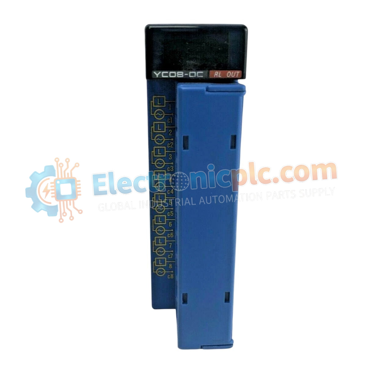
The Yokogawa F3YC08-0C, also cataloged as the F3YC08 Relay Output Module, operates as a dedicated hardware component for switching discrete electrical loads within FA-M3 industrial control platforms.
| Parameter | Specification |
|---|---|
| Model | F3YC08-0C |
| Brand | Yokogawa |
| Origin | Japan |
| Weight | 0.3kg |
| Dimensions | 10.2 cm x 12.7 cm x 5.1 cm |
| Operating Temp | 0 to 55 deg C |
| Output Type | Relay contact |
| Number of Outputs | 8 |
| Rated Load Voltage | 5-24 V DC / 100-240 V AC |
| Max Load Current | 2 A per point |
The F3YC08-0C provides eight independent relay output channels, utilizing mechanical isolation to decouple high-voltage field loads from the low-voltage controller backplane. The module architecture is designed for high-density applications, ensuring deterministic state transition times of 10 ms maximum for both OFF-to-ON and ON-to-OFF cycles. Each channel is electrically independent, allowing for the concurrent management of diverse voltage levels (DC and AC) without the risk of cross-channel interference or ground loop propagation.
Q: Are the output relays replaceable in the field if a contact fails?
A: No. The relays are integrated onto the printed circuit board assembly. If a channel failure occurs, the entire module must be replaced to ensure system reliability and safety.
Q: Is there an internal protection circuit for inductive loads?
A: The module does not include internal snubber or flyback protection for inductive loads. External surge suppression (such as diodes for DC or RC networks for AC) must be installed at the load side to prevent contact erosion and arcing.


