My Cart
0 items
Genuine Automation Parts | Worldwide Express Delivery | 12-Month Warranty — [GET A QUOTE]

Configured for discrete control in FA-M3 PLC platforms, the YOKOGAWA F3YD14-5B (F3YD14-5B Digital Output Module) provides direct physical and electrical execution of transistor-based switching for field-side loads.
Availability: In stock
Reliable Worldwide Delivery
30-Day Money-Back Guarantee
Need more details? Read our fullShipping PolicyandRefund Policy.


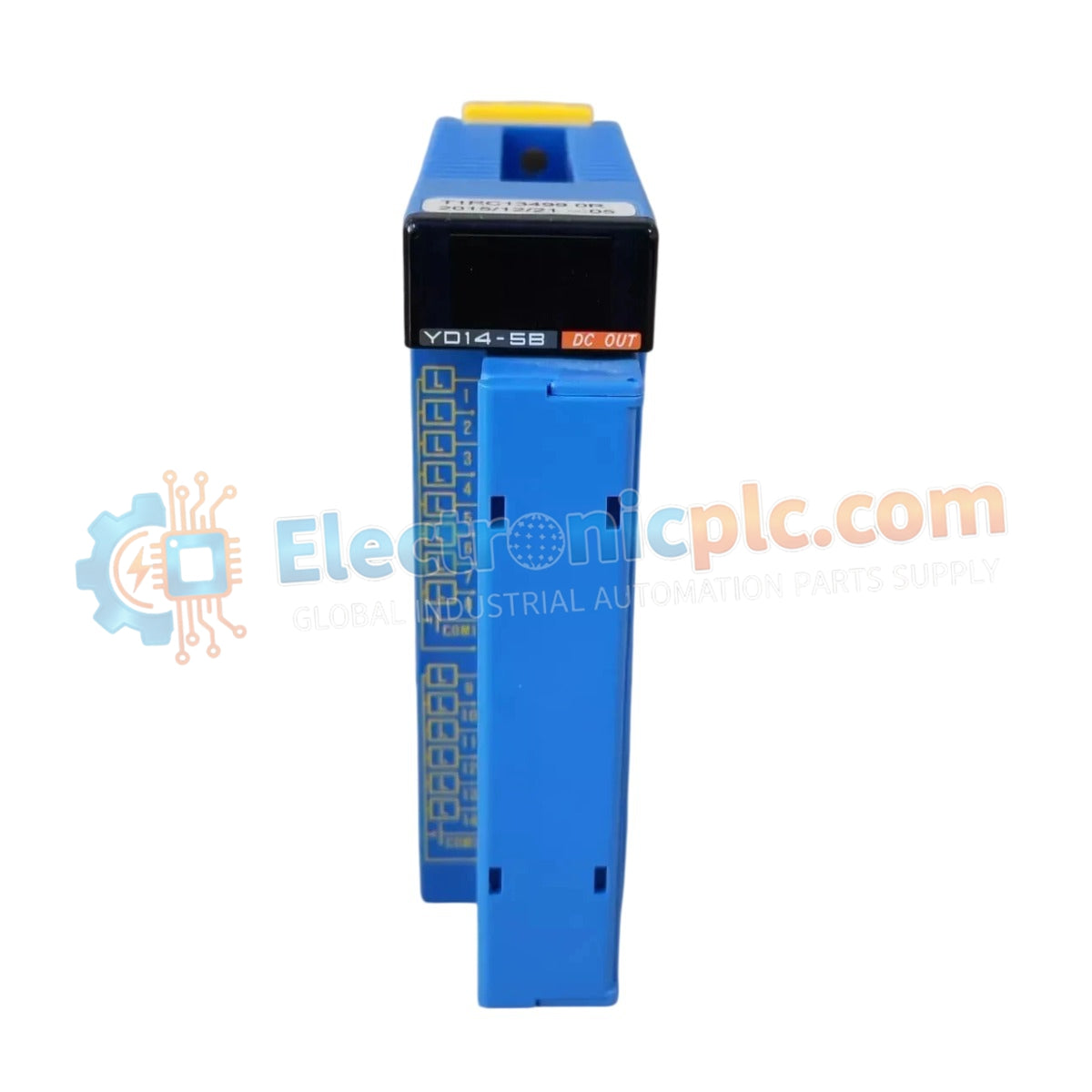
Configured for discrete control in FA-M3 PLC platforms, the YOKOGAWA F3YD14-5B (F3YD14-5B Digital Output Module) provides direct physical and electrical execution of transistor-based switching for field-side loads.
| Parameter | Specification |
|---|---|
| Model | F3YD14-5B |
| Brand | YOKOGAWA |
| Origin | Japan |
| Weight | 0.4kg |
| Dimensions | Standard FA-M3 Module Form Factor |
| Operating Temp | 0 deg C to 55 deg C |
| Power Consumption | Not specified (Internal bus draw) |
| Output Points | 14 channels |
| Output Type | Source-type Transistor |
| Output Current | 0.5 A per point (4.0 A total) |
| Isolation | Photocoupler isolation |
The F3YD14-5B module facilitates deterministic output signaling within the FA-M3 architecture. It utilizes channel-to-channel isolation architecture to prevent back-feed damage from inductive loads such as solenoids and relays. The integrated photocoupler isolation ensures that field-side voltage spikes do not propagate into the internal system backplane, maintaining overall loop integrity during high-frequency switching operations.
Q: Can the F3YD14-5B module be hot-swapped while the output load is powered?
A: No, the module does not support online removal. Power to the 40-pin connector and the base unit must be disconnected to prevent damage to the output transistors and backplane communication bus.
Q: How should inductive loads be suppressed when connected to this module?
A: Given the transistor-based source-type output, external flyback diodes or appropriate RC snubbers are required across inductive loads to prevent transient voltage damage to the switching transistors.


