
My Cart
0 items
Genuine Automation Parts | Worldwide Express Delivery | 12-Month Warranty — [GET A QUOTE]

Configured for versatile signal management in process control platforms, the Yokogawa FCA4*A (FCA4*A Universal I/O Module) provides direct physical/electrical execution of both analog and digital signal acquisition.
Availability: Low stock: 99 left
Reliable Worldwide Delivery
30-Day Money-Back Guarantee
Need more details? Read our fullShipping PolicyandRefund Policy.

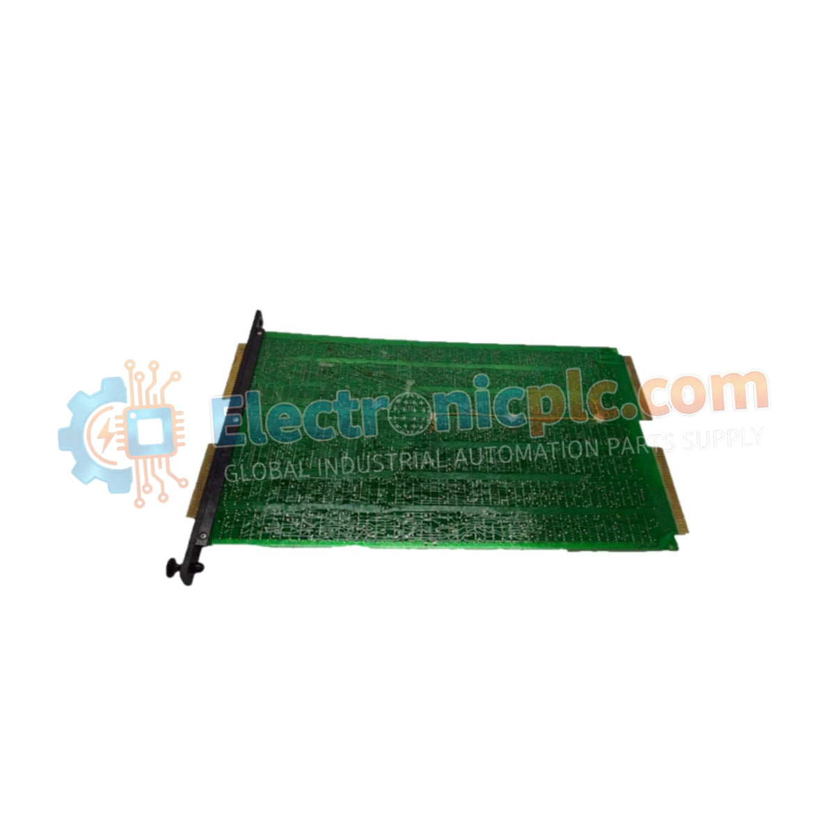
Configured for versatile signal management in process control platforms, the Yokogawa FCA4*A (FCA4*A Universal I/O Module) provides direct physical/electrical execution of both analog and digital signal acquisition.
The FCA4*A series utilizes a flexible suffix structure to define specific I/O configurations. Ensure the full catalog number is verified against the system requirements to confirm the appropriate channel mapping and signal type compatibility.
| Parameter | Specification |
|---|---|
| Model | FCA4*A |
| Brand | Yokogawa |
| Origin | Japan |
| Weight | Consult technical manual |
| Dimensions | Compact industrial form factor |
| Operating Temp | -20 to +60 deg C |
| Power Consumption | Refer to system backplane power budget |
| Power Supply | 24 VDC |
| I/O Type | Universal (Analog and Digital) |
The module employs a universal I/O architecture, allowing the system to interface with a wide range of field instrumentation without the need for fixed-function hardware. This flexibility is managed through internal signal conditioning circuits that automatically adjust impedance and excitation levels based on the configured signal type. The robust, industrial-grade construction is engineered to maintain signal integrity under variable temperature conditions, while the plug-and-play mechanical design facilitates rapid deployment and modular replacement within control cabinets.
Q: Does the universal I/O configuration require physical jumpers for signal type selection?
A: The module is designed for software-defined configuration. Signal types (analog/digital) and ranges are generally selected through the system engineering software, eliminating the need for manual hardware adjustments.
Q: Can this module be mounted directly in hazardous area zones?
A: While the module meets relevant industrial performance standards, ensure it is installed within an appropriate enclosure or used with certified barriers if the installation zone requires intrinsic safety or explosion-proof ratings.

