
My Cart
0 items
Genuine Automation Parts | Worldwide Express Delivery | 12-Month Warranty — [GET A QUOTE]

Configured for high-reliability signal switching in process control platforms, the Yokogawa GRO-1241 (GRO-1241 Digital Output Module) provides direct physical/electrical execution of logic-driven state changes for field instrumentation.
Availability: Low stock: 99 left
Reliable Worldwide Delivery
30-Day Money-Back Guarantee
Need more details? Read our fullShipping PolicyandRefund Policy.
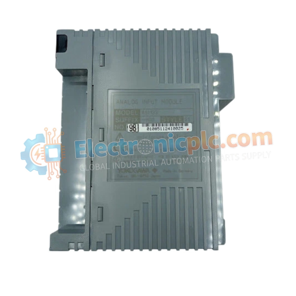
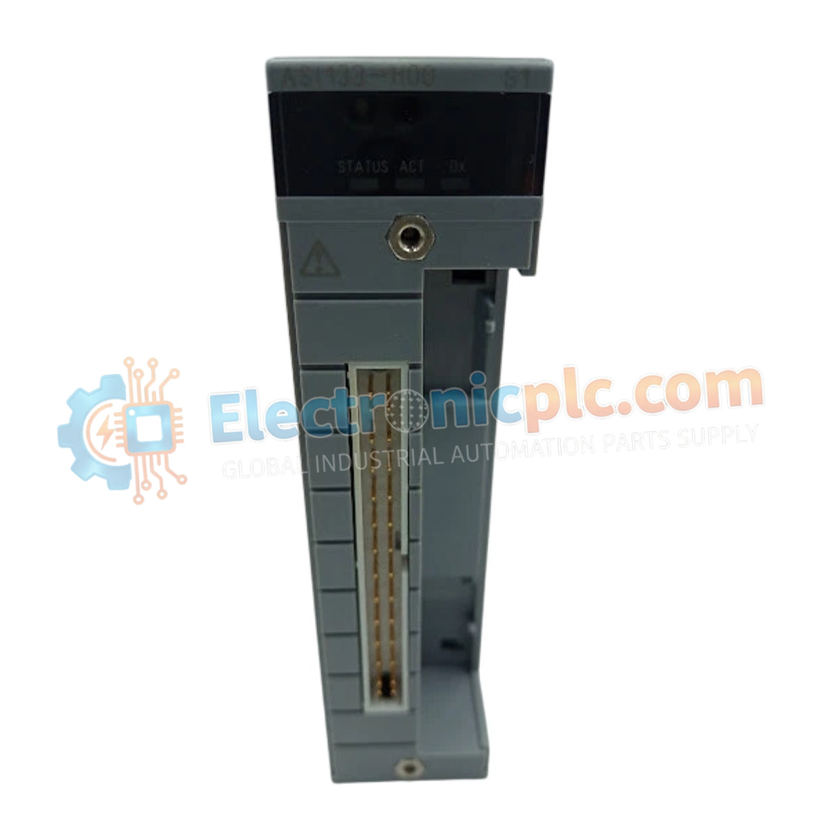
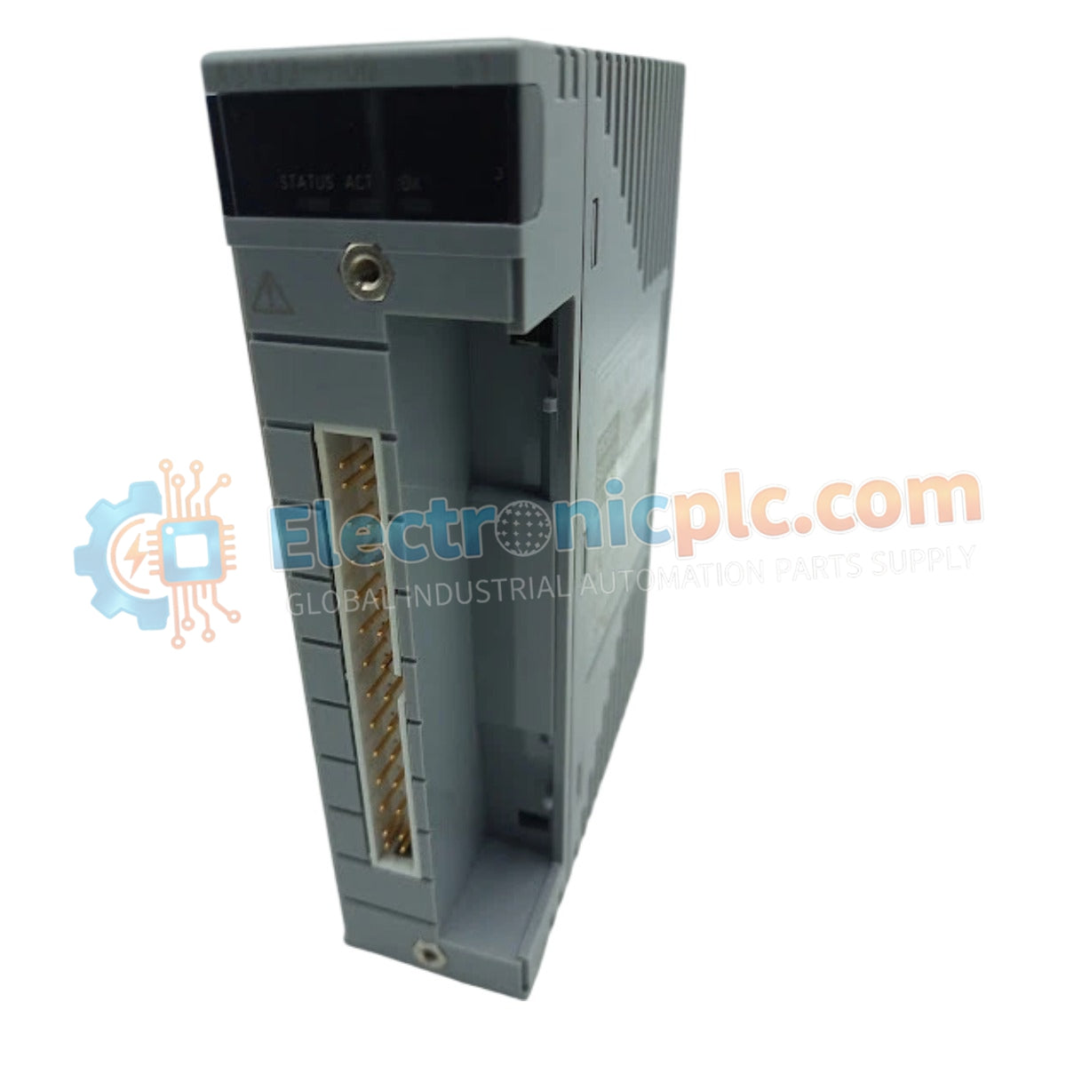
Configured for high-reliability signal switching in process control platforms, the Yokogawa GRO-1241 (GRO-1241 Digital Output Module) provides direct physical/electrical execution of logic-driven state changes for field instrumentation.
| Parameter | Specification |
|---|---|
| Model | GRO-1241 |
| Brand | Yokogawa |
| Origin | Japan |
| Weight | Standard DCS module form factor |
| Dimensions | Industrial cabinet mount dimensions |
| Operating Temp | Industrial grade (consult system manual) |
| Power Consumption | Refer to backplane power budget |
| Output Type | Digital (Actuator/Relay/Alarm control) |
| Architecture | Modular design |
The GRO-1241 serves as the final control element interface, translating binary controller logic into physical electrical outputs. Its design focuses on stability and durability, ensuring that critical process elements such as actuators and safety relays receive consistent voltage signals despite the electrical noise common in industrial environments. The modular architecture enables seamless scaling, allowing for the precise management of multiple output channels within the Yokogawa automation ecosystem.
Q: Does the GRO-1241 include built-in protection against inductive kickback from relays?
A: The module is designed with internal suppression circuits to mitigate transient voltage spikes (flyback) when switching inductive loads. However, for large solenoid or motor contactors, verify the need for additional external snubber circuits in the system documentation.
Q: Can the output voltage be configured for different field device requirements?
A: The module features a configurable output voltage range. Ensure that the module's voltage setting matches the power requirements of the connected field devices during the engineering configuration phase.


