
My Cart
0 items
Genuine Automation Parts | Worldwide Express Delivery | 12-Month Warranty — [GET A QUOTE]

Configured for high-density signal interconnection, the YOKOGAWA KS1-07*B (KS1 Signal Cable) provides direct physical/electrical execution for data transit between field terminal boards and I/O module assemblies within CENTUM series control architectures. This...
Availability: In stock
Reliable Worldwide Delivery
30-Day Money-Back Guarantee
Need more details? Read our fullShipping PolicyandRefund Policy.
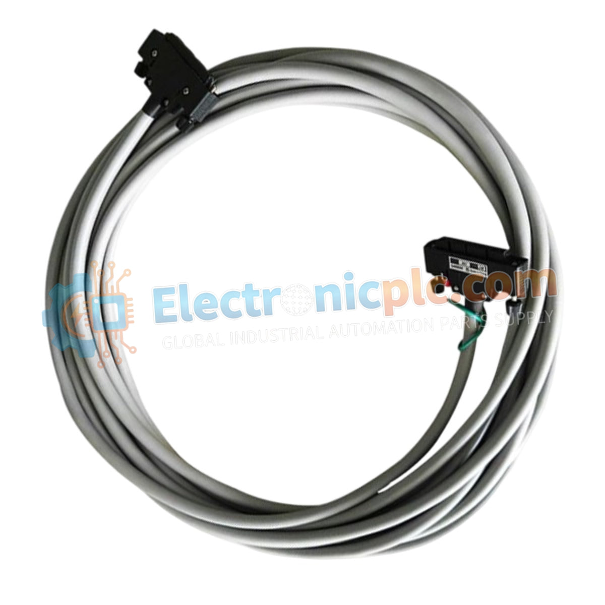
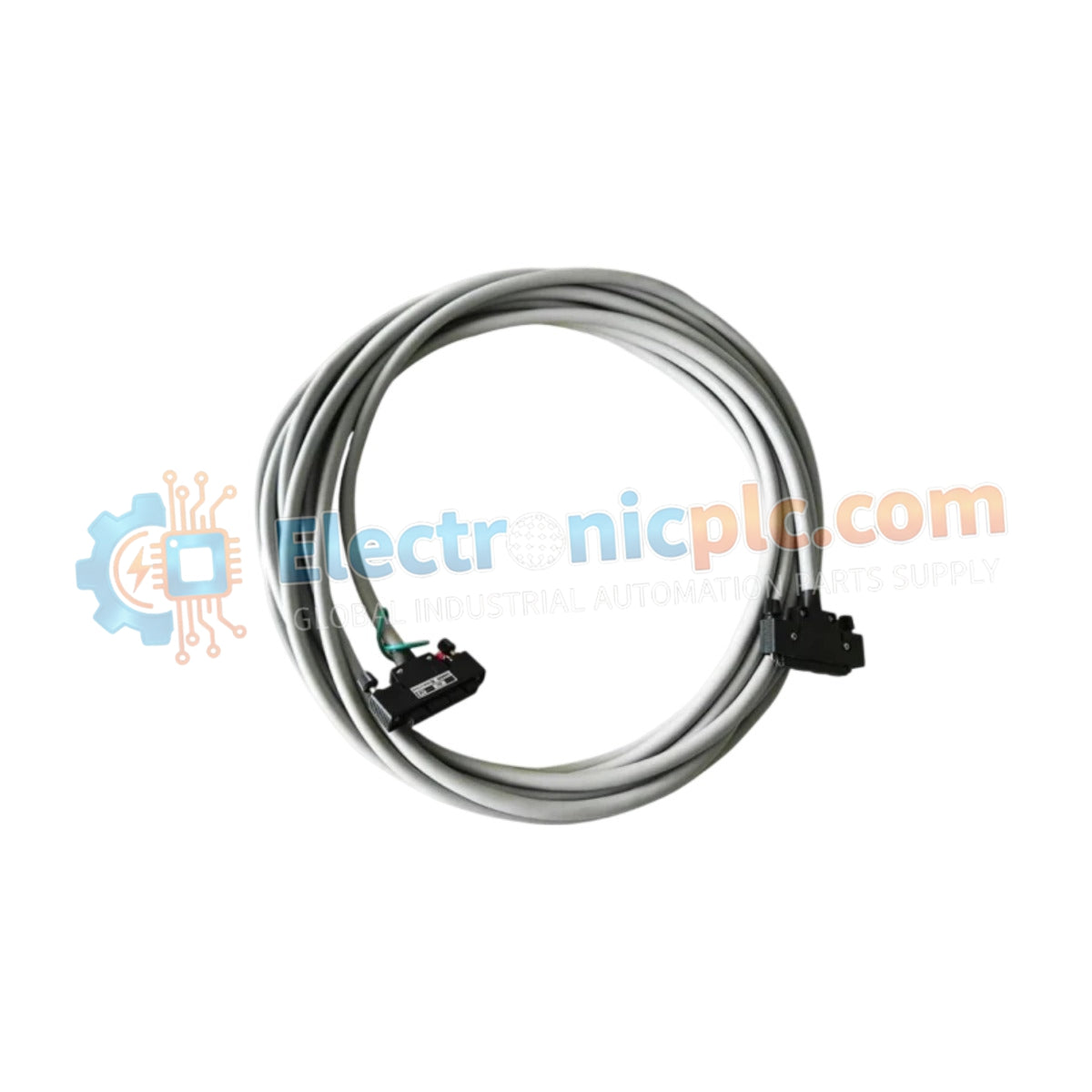
Configured for high-density signal interconnection, the YOKOGAWA KS1-07*B (KS1 Signal Cable) provides direct physical/electrical execution for data transit between field terminal boards and I/O module assemblies within CENTUM series control architectures. This cable assembly utilizes a 40-pin to 40-pin interface to maintain deterministic signal paths across the distributed control system.
The KS1-07*B is defined by the following configuration attributes:
KS1: Base model designation for the multi-pin signal cable.
07: Specifies a cable length of 7 meters.
*B: Denotes Style B construction, ensuring compatibility with current CENTUM VP and CS series interface standards.
| Parameter | Specification |
| Model | KS1-07*B |
| Brand | YOKOGAWA |
| Origin | Japan |
| Weight | 0.9 kg |
| Dimensions | 25.4 cm x 5.1 cm x 38.1 cm |
| Pin Configuration | 40-pin to 40-pin |
| Cable Type | Multi-core Signal Cable |
| Operating Temp | -20 deg C to 70 deg C |
The KS1-07*B is engineered to facilitate reliable data exchange by maintaining consistent electrical performance across its 40-pin interface. This high-density connection supports the propagation of analog and digital signals, ensuring that signal amplitude remains within the strictly defined parameters required for CENTUM VP fault-tolerant networks. The cable assembly features integrated shielding to mitigate electromagnetic interference (EMI) risks in high-noise industrial cabinet environments, preserving signal fidelity for process control instrumentation.
Q: Is this cable suitable for use in high-vibration areas?
A: Yes, the cable connectors are designed for secure attachment to module backplanes and terminal boards, providing mechanical retention that resists loosening due to industrial vibration profiles. Ensure the connector locking mechanisms are fully engaged upon installation.
Q: Can multiple KS1 cables be connected in series to extend the length?
A: No, the KS1 cable assembly is designed for point-to-point connections between a terminal board and an I/O module. Extending the distance via daisy-chaining is not recommended as it increases contact resistance and potential for signal degradation.
Inspect both 40-pin connectors for bent or oxidized pins prior to installation. A compromised pin connection can lead to intermittent I/O communication errors or signal loss.
When routing the cable, maintain a minimum bending radius as specified by the cable construction to prevent internal conductor fatigue or shield damage.
Keep the signal cable physically separated from high-voltage power lines and AC motor drive cabling to minimize inductive noise coupling.
Align the connector vertically with the port on the I/O module or terminal board and push firmly until the locking mechanism is fully secured.
Secure the cable to the cabinet framework using cable ties or management channels, ensuring that the connector is not under physical tension or strain.


