My Cart
0 items
Genuine Automation Parts | Worldwide Express Delivery | 12-Month Warranty — [GET A QUOTE]

Configured for high-density signal interconnects within DCS and PLC control architectures, the YOKOGAWA KS1-10*B (KS1 Signal Cable) provides direct physical and electrical execution of multi-channel data transmission between I/O modules...
Availability: Low stock: 99 left
Reliable Worldwide Delivery
30-Day Money-Back Guarantee
Need more details? Read our fullShipping PolicyandRefund Policy.
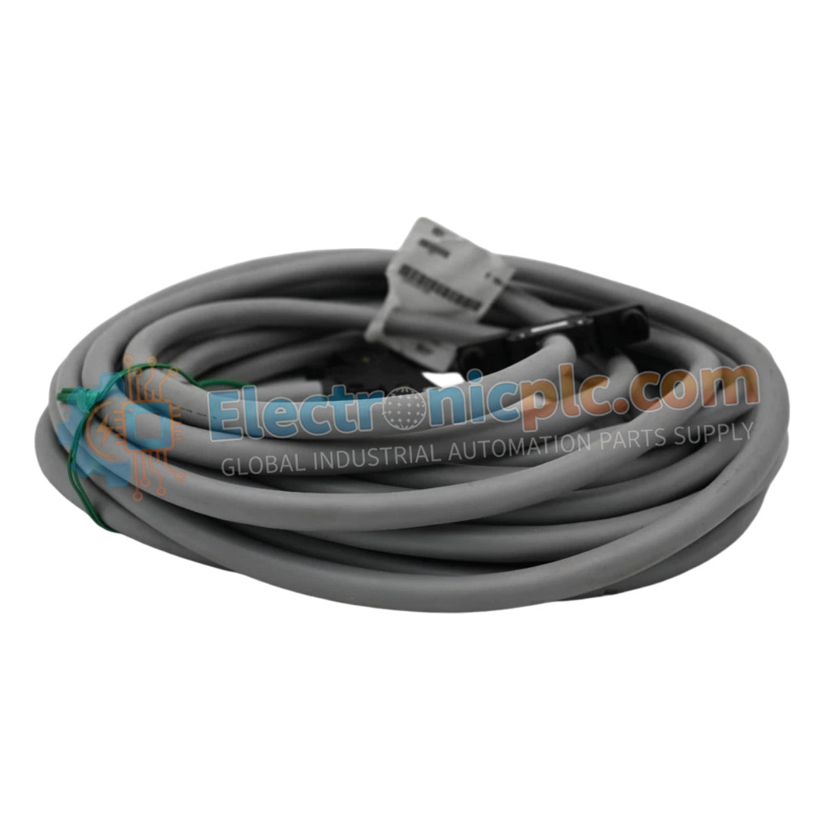

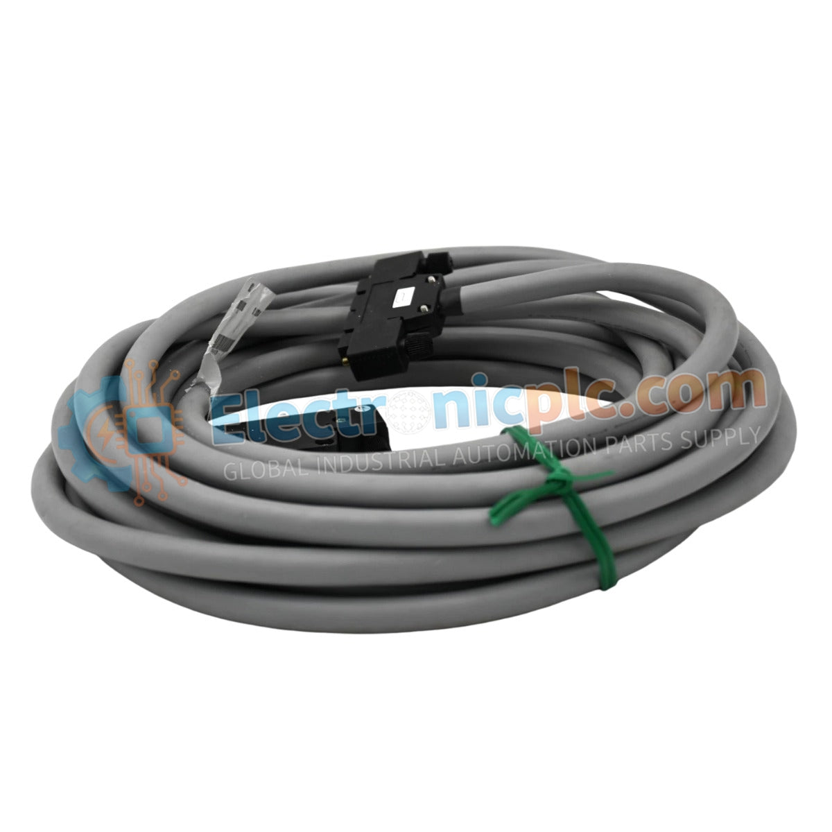
Configured for high-density signal interconnects within DCS and PLC control architectures, the YOKOGAWA KS1-10*B (KS1 Signal Cable) provides direct physical and electrical execution of multi-channel data transmission between I/O modules and field interface panels.
The KS1 series utilizes standardized nomenclature to define connectivity specifications and physical length requirements:
| Parameter | Specification |
|---|---|
| Model | KS1-10*B |
| Brand | YOKOGAWA |
| Origin | Japan |
| Weight | 1.2 kg |
| Dimensions | 10 meters length |
| Operating Temp | -20 deg C to +70 deg C |
| Power Consumption | Passive (Signal transmission) |
| Connector Type | 40-pin to 40-pin |
The KS1 assembly utilizes a multi-conductor structure designed for low-latency signal coupling between control hardware and field termination units. Each conductor is engineered to maintain consistent electrical impedance, minimizing signal degradation and cross-talk across high-density I/O channels. The connectors feature secure latching mechanisms designed to prevent accidental disconnection caused by mechanical vibration or thermal expansion within the cabinet. Integrated shielding layers, when correctly terminated at the module chassis, function to mitigate electromagnetic interference (EMI) and radio frequency interference (RFI) typical in industrial control environments.
Q: Can the KS1-10*B cable be used in extreme ambient temperature conditions?
A: The cable is rated for operation between -20 deg C and +70 deg C. Installation outside of these parameters will compromise the insulation jacket and conductor integrity over time.
Q: Is this cable compatible with all 40-pin Yokogawa I/O modules?
A: The KS1-10*B is designed for standard 40-pin I/O configurations. Always verify the specific terminal assignment and Style B compatibility against the module datasheet prior to connection.


