My Cart
0 items
Genuine Automation Parts | Worldwide Express Delivery | 12-Month Warranty — [GET A QUOTE]

The YOKOGAWA KS1-20*A is a high-density, multi-pair signal cable designed specifically for connecting Yokogawa field terminal boards to I/O modules within CENTUM and ProSafe-RS control systems. It is engineered to...
Availability: Low stock: 99 left
Reliable Worldwide Delivery
30-Day Money-Back Guarantee
Need more details? Read our fullShipping PolicyandRefund Policy.
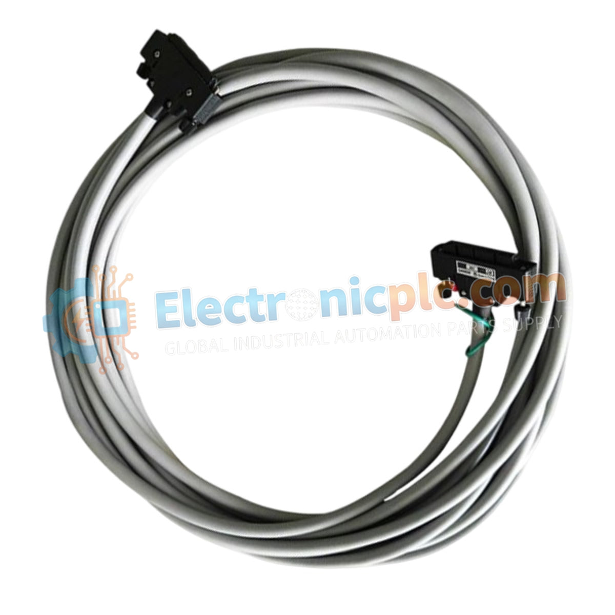
The YOKOGAWA KS1-20*A is a high-density, multi-pair signal cable designed specifically for connecting Yokogawa field terminal boards to I/O modules within CENTUM and ProSafe-RS control systems. It is engineered to maintain signal integrity for both analog and digital I/O in demanding industrial automation environments.
| Parameter | Specification |
|---|---|
| Model | KS1-20*A |
| Brand | YOKOGAWA |
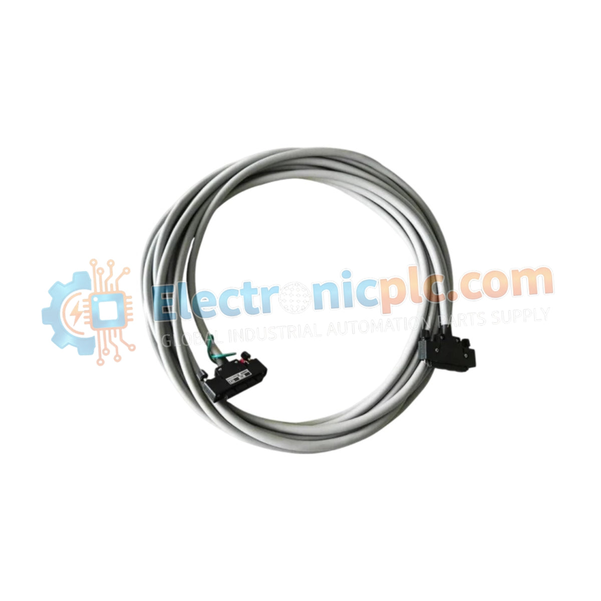
| Cable Type | 20-pair shielded cable |
| Connectivity | 40-pin connectors (both ends) |
| Available Lengths | 1m, 2m, 3m, 4m, 8m, 20m |
| Operating Temp | -10°C to +60°C |
| Storage Temp | -20°C to +70°C |
| Application | Analog/Digital signal transmission |
The KS1-20*A utilizes a 20-pair shielded construction, which is essential for minimizing electromagnetic interference (EMI) and crosstalk in high-density signal environments. The shielding provides a robust barrier against external noise sources commonly found in plant cabinets, ensuring that control loops and sensor data remain accurate. The cable is designed for flexibility and durability, allowing it to withstand the thermal and physical stresses typical of long-term industrial operations.
Q: Can I use the KS1-20A for custom lengths outside of the standard options? A: The KS1-20A is manufactured in fixed lengths (1m through 20m) to ensure the electrical characteristics, such as impedance and resistance, remain consistent. Modifying these cables is not recommended as it may compromise signal integrity and system-certified performance.
Q: What is the primary purpose of the 40-pin connector configuration?
A: The 40-pin connector is designed to match the high-density terminal boards used in Yokogawa’s distributed control systems, allowing for a "plug-and-play" connection that significantly reduces field wiring time and potential human error during installation.


