My Cart
0 items
Genuine Automation Parts | Worldwide Express Delivery | 12-Month Warranty — [GET A QUOTE]

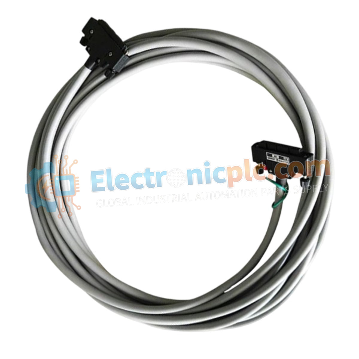
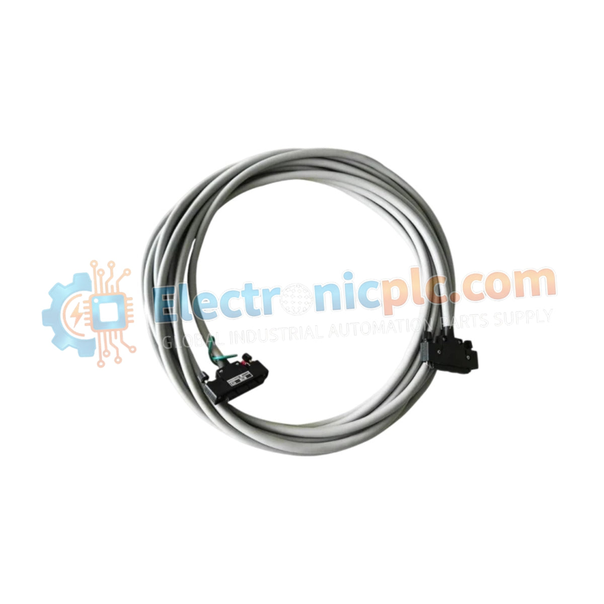
Configured for high-density signal interconnects in DCS platforms, the Yokogawa KS1-20 (KS1-20 Signal Cable) provides direct physical/electrical execution of 40-pin to 40-pin signal transmission.
| Parameter | Specification |
|---|---|
| Model | KS1-20 |
| Brand | Yokogawa |
| Origin | Japan |
| Weight | 2.0 kg |
| Dimensions | 20 meter length |
| Operating Temp | -20 to 70 deg C |
| Power Consumption | Passive component (N/A) |
| Connector Type | 40-pin to 40-pin |
| Transmission | Multi-core signal interconnect |
The cable functions as a standardized interconnect for Yokogawa system modules, maintaining consistent electrical characteristics across the entire 20-meter run. The 40-pin connector interfaces are engineered to provide secure contact and low impedance for high-density I/O arrays, ensuring that signal transmission between field termination assemblies and system backplanes remains robust. The construction utilizes industrial-grade insulation rated for operation between -20 deg C and 70 deg C, offering durability in standard control cabinet and cable tray environments while minimizing crosstalk and capacitive interference between signal lines.
Q: Can this 20-meter cable be extended by splicing?
A: Splicing is strongly discouraged as it introduces impedance discontinuities, potential signal reflection, and significant increases in resistance that can compromise signal accuracy and I/O timing.
Q: Is the cable jacket rated for outdoor or chemical exposure?
A: The KS1 series is designed for indoor industrial control environments. Exposure to harsh chemicals, UV light, or extreme moisture may degrade the jacket material and is not recommended.