
My Cart
0 items
Genuine Automation Parts | Worldwide Express Delivery | 12-Month Warranty — [GET A QUOTE]

Configured for high-density signal propagation in YOKOGAWA control networks, the YOKOGAWA KS9-10*B (KS9 Signal Cable) provides direct physical data link execution between field interface modules and system controllers.
Availability: In stock
Reliable Worldwide Delivery
30-Day Money-Back Guarantee
Need more details? Read our fullShipping PolicyandRefund Policy.
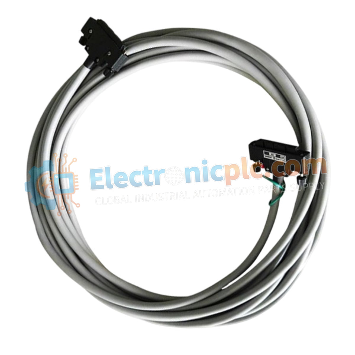
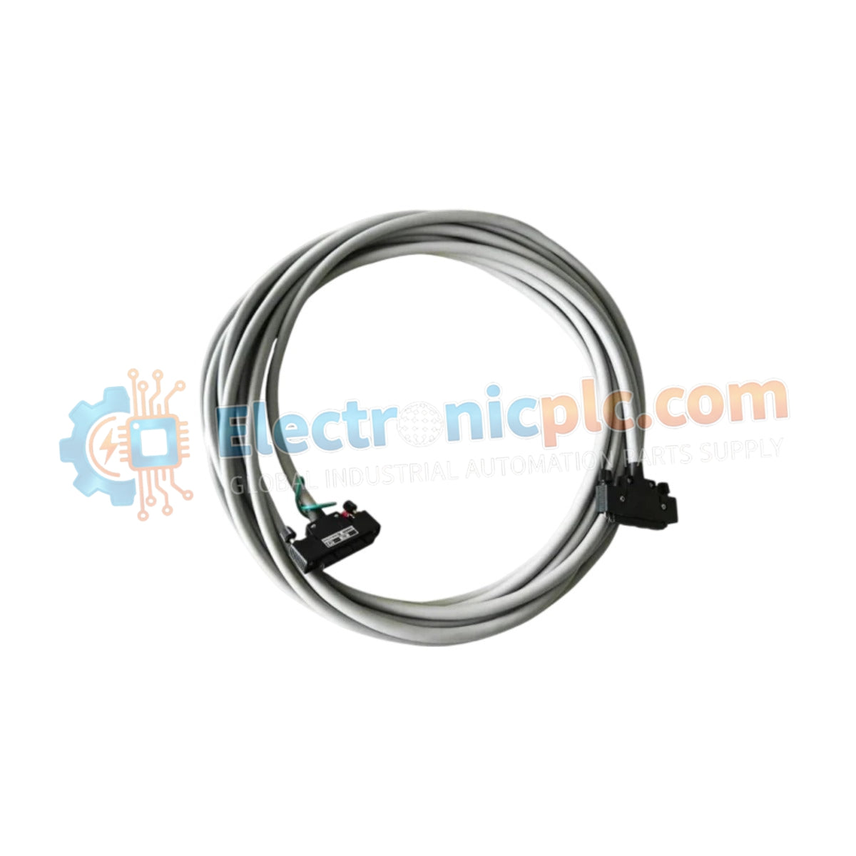
Configured for high-density signal propagation in YOKOGAWA control networks, the YOKOGAWA KS9-10*B (KS9 Signal Cable) provides direct physical data link execution between field interface modules and system controllers.
| Model | Suffix / Style Code | Description |
|---|---|---|
| KS9 | 10 | Cable length 10 meters |
| KS9 | *B | Style B |
| Parameter | Specification |
|---|---|
| Model | KS9-10*B |
| Brand | YOKOGAWA |
| Origin | Japan |
| Weight | 3 kg |
| Dimensions | 10 meters length |
| Operating Temp | -20 deg C to 60 deg C |
| Power Consumption | N/A (Passive interconnect) |
| Connector Type | 50-pin to 50-pin interface |
The KS9-10*B cable assembly is engineered to maintain signal integrity for 4-20 mA HART loop protocol architectures and high-density digital I/O arrays. The physical construction utilizes shielded multi-core cabling to facilitate channel-to-channel isolation, minimizing crosstalk between adjacent conductors. This design ensures that analog and discrete signals remain within specified accuracy tolerances when transmitted over the 10 meter span between field terminal blocks and system I/O cards.
Q: Is the KS9-10B cable compatible with older generations of system interface modules? A: The compatibility of the KS9-10B (Style B) depends on the specific pinout configuration of the legacy module. Verify the interface requirements against the system documentation before installation to ensure electrical pin-mapping alignment.
Q: Can this cable be used in cable trays alongside 220 VAC power lines?
A: No. Signal cables must be routed in dedicated instrumentation trays. Maintain a minimum separation of 300 mm from high-voltage power lines to prevent electromagnetic interference (EMI) and induced noise on the data lines.


