
My Cart
0 items
Genuine Automation Parts | Worldwide Express Delivery | 12-Month Warranty — [GET A QUOTE]

Configured for high-density signal acquisition in industrial control platforms, the YOKOGAWA NFA143-H50/A4AS0 (NFA143 Analog Input Module) provides direct physical/electrical execution for 4-20 mA process loops. This hardware component...
Availability: In stock
Reliable Worldwide Delivery
30-Day Money-Back Guarantee
Need more details? Read our fullShipping PolicyandRefund Policy.

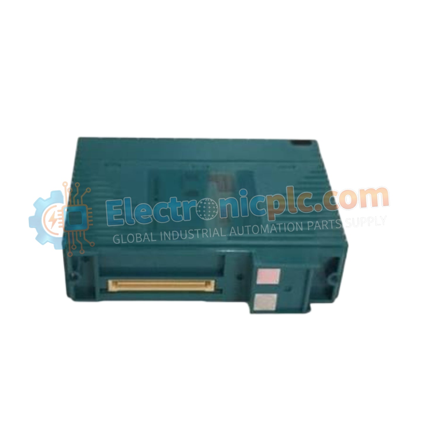
Configured for high-density signal acquisition in industrial control platforms, the YOKOGAWA NFA143-H50/A4AS0 (NFA143 Analog Input Module) provides direct physical/electrical execution for 4-20 mA process loops. This hardware component processes 16 isolated channels, ensuring deterministic data acquisition and robust signal integrity across distributed control systems.
The NFA143-H50/A4AS0 is defined by the following configuration attributes:
NFA143: Base model designation for the 16-channel analog input module.
H50: Specifies the standard operating configuration for Yokogawa process control systems.
A4AS0: Designates the specific terminal interface and environmental hardening level for the assembly.
| Parameter | Specification |
| Model | NFA143-H50/A4AS0 |
| Brand | YOKOGAWA |
| Origin | Japan |
| Weight | 0.3 kg |
| Dimensions | Standard Module Enclosure |
| Operating Temp | 0 deg C to 60 deg C |
| Power Consumption | 230 mA (5 V DC), 540 mA (24 V DC) |
| Input Channels | 16 Isolated |
| Data Update Cycle | 10 ms |
| Accuracy | +/- 0.1% of full scale |
The NFA143-H50/A4AS0 is optimized for 4-20 mA HART loop protocol connectivity. It features channel-to-channel isolation and a dielectric withstand voltage of 1500 V AC, ensuring that common-mode electrical noise does not degrade signal accuracy in multi-loop instrumentation cabinets. The hardware utilizes precision current sensing to mitigate temperature drift, maintaining stability within ±0.01% per deg C, which is essential for consistent control performance.
Q: Can the NFA143-H50/A4AS0 support field devices that require external power?A: The module is designed to accept 4-20 mA current signals. For field devices requiring external power, ensure the loop wiring includes an appropriate power source and that current sensing is performed in series within the loop.
Q: How does the module handle overcurrent conditions?A: The NFA143-H50/A4AS0 includes built-in overcurrent protection to safeguard the internal A/D conversion circuitry from fault currents exceeding the 24 mA maximum input threshold.
Verify that the system backplane power is within the specified 24.0 V DC to 25.5 V DC range before module insertion to prevent potential logic voltage dips.
Terminate 4-20 mA signals using shielded twisted-pair cabling. Ground the shield at the cabinet entry point to the instrument ground bus to minimize EMI susceptibility.
Inspect terminal connections for mechanical security; loose connections on current loops can introduce significant signal noise and intermittent measurement errors.
Maintain a minimum ambient airflow clearance around the module housing, as the higher current consumption (540 mA at 24 V DC) may contribute to localized heat generation in high-density cabinets.
After installation, execute a diagnostic loop check using the DCS controller software to verify that the digitized values correlate accurately with the measured field current levels.

