My Cart
0 items
Genuine Automation Parts | Worldwide Express Delivery | 12-Month Warranty — [GET A QUOTE]

The YOKOGAWA NFAI143, also cataloged as the NFAI143 Analog Input Module, operates as a dedicated hardware component for high-precision sensor signal acquisition within CENTUM VP control systems.
Availability: Low stock: 99 left
Reliable Worldwide Delivery
30-Day Money-Back Guarantee
Need more details? Read our fullShipping PolicyandRefund Policy.


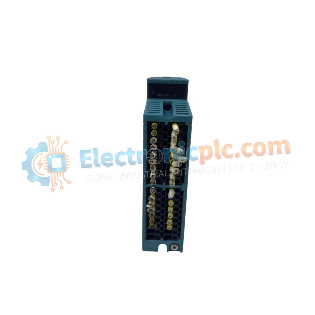
The YOKOGAWA NFAI143, also cataloged as the NFAI143 Analog Input Module, operates as a dedicated hardware component for high-precision sensor signal acquisition within CENTUM VP control systems.
| Parameter | Specification |
|---|---|
| Model | NFAI143 |
| Brand | YOKOGAWA |
| Origin | Japan |
| Weight | 0.3 kg |
| Dimensions | Standard DIN-rail mountable module |
| Operating Temp | -20 deg C to +70 deg C |
| Power Consumption | 24 V DC |
| Input Channels | 4 |
| Resolution | 16 bits |
The NFAI143 module facilitates the conversion of field instrumentation signals into high-resolution digital data. The architecture supports 4-20 mA and 0-20 mA inputs with a measurement range reaching 24 mA. To ensure measurement precision, the module executes automatic cold junction compensation (CJC) for temperature-related variables and maintains an accuracy rating of ±0.1% of the reading. Galvanic isolation is implemented between the field input terminals and the internal system backplane to suppress common-mode noise and prevent ground loops in extensive industrial wiring networks.
Q: Can the NFAI143 be configured for different input signal ranges per channel?
A: Yes, the module supports software-defined configuration for input ranges across its 4 channels, allowing for flexible integration of various 4-20 mA and 0-20 mA loop-powered devices.
Q: Is this module capable of performing under high-temperature industrial conditions?
A: The NFAI143 is engineered for operation within a range of -20 deg C to +70 deg C, providing stable performance in demanding cabinet environments without degradation of accuracy.


