My Cart
0 items
Genuine Automation Parts | Worldwide Express Delivery | 12-Month Warranty — [GET A QUOTE]

Configured for high-density signal distribution in distributed control systems, the Yokogawa NFAI543-S50 (NFAI543 Analog Output Module) provides direct physical/electrical execution of 16-channel 4-20 mA control loops. This module serves as...
Availability: Low stock: 99 left
Reliable Worldwide Delivery
30-Day Money-Back Guarantee
Need more details? Read our fullShipping PolicyandRefund Policy.


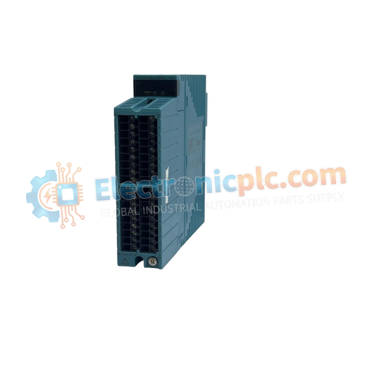
Configured for high-density signal distribution in distributed control systems, the Yokogawa NFAI543-S50 (NFAI543 Analog Output Module) provides direct physical/electrical execution of 16-channel 4-20 mA control loops. This module serves as the primary interface for driving field actuators, ensuring precise current-based signal delivery with configurable fallback states for loop-integrity management.
| Parameter | Specification |
|---|---|
| Model | NFAI543-S50 |
| Brand | Yokogawa |
| Origin | Japan |
| Weight | 0.4 kg |
| Dimensions | Standard I/O Module Form Factor |
| Operating Temp | Consult System Environmental Specifications |
| Power Consumption | 230 mA (5 VDC) / 540 mA (24 VDC) |
| Output Channels | 16 (Isolated) |
| Output Signal | 4-20 mA |
| Load Resistance | 0 to 750 Ohm |
The NFAI543-S50 architecture utilizes channel-to-channel isolation to maintain signal separation and minimize ground-path noise across the 16 independent loops. The module supports HART communication, allowing for bidirectional data exchange with intelligent field devices simultaneously with the analog control signal. To ensure process safety during logic communication loss, the module features configurable output fallback states for every individual channel. The signal processing chain provides a 10 ms data refresh cycle and a 100 ms output step response, optimized for maintaining stability in complex industrial control loops.
Q: Can the output fallback state be configured differently for each of the 16 channels?
A: Yes. The NFAI543-S50 architecture supports independent fallback configuration per channel, allowing for granular control of actuator positioning (e.g., hold last value, drive to zero, or custom safety setpoint) upon loss of communication or system fault.
Q: What is the significance of the 1500 VAC withstanding voltage specification?
A: This specification verifies the galvanic isolation barrier between the field-side output terminals and the internal system bus. It ensures that transients or ground potential differences on the field wiring do not damage the internal backplane components.


