
My Cart
0 items
Genuine Automation Parts | Worldwide Express Delivery | 12-Month Warranty — [GET A QUOTE]

Configured for industrial process measurement in DCS platforms, the Yokogawa NFAR181-S50 (NFAR181-S50 RTD Input Module) provides direct signal acquisition and galvanic isolation for RTD sensor inputs.
Availability: Low stock: 99 left
Reliable Worldwide Delivery
30-Day Money-Back Guarantee
Need more details? Read our fullShipping PolicyandRefund Policy.
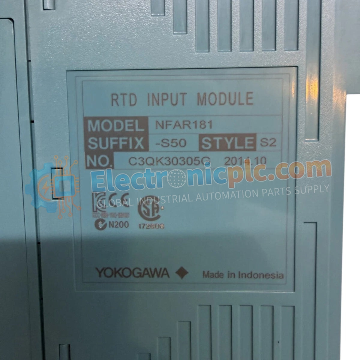

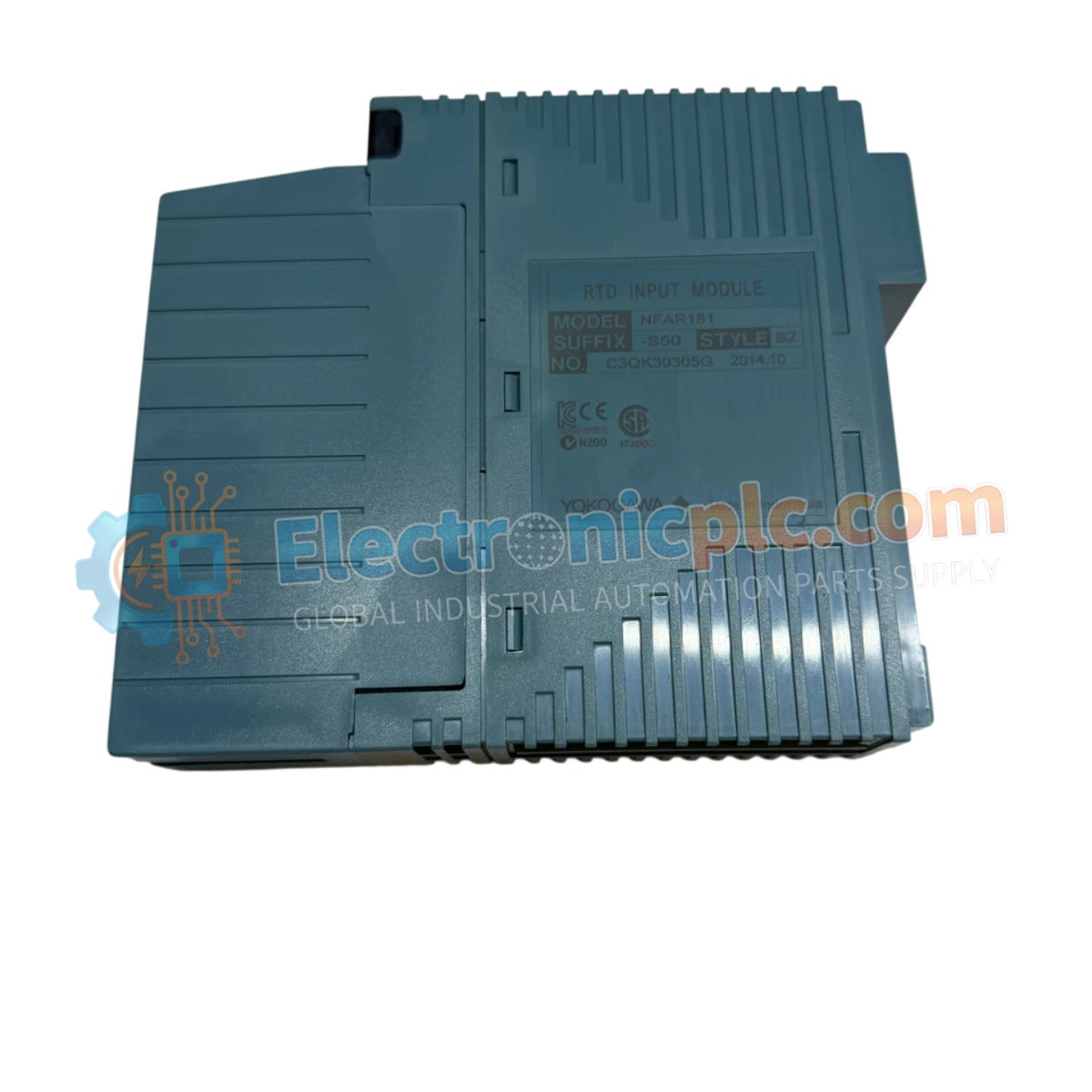
Configured for industrial process measurement in DCS platforms, the Yokogawa NFAR181-S50 (NFAR181-S50 RTD Input Module) provides direct signal acquisition and galvanic isolation for RTD sensor inputs.
| Parameter | Specification |
|---|---|
| Model | NFAR181-S50 |
| Brand | Yokogawa |
| Origin | Japan |
| Weight | 0.2 kg |
| Dimensions | Standard Yokogawa I/O card form factor |
| Operating Temp | Standard industrial range (refer to system manual) |
| Power Consumption | 450 mA (5 V DC) |
| Input Channels | 12, isolated |
| Input Signal Type | Pt100 (3-wire) |
| Input Range | -200 to 800 deg C |
| Accuracy | +/- 0.15 deg C |
| Withstanding Voltage | 1500 V AC (input to system) |
The module maintains signal integrity through active cold junction compensation (CJC) for temperature measurement circuits and provides robust channel-to-channel isolation. The input resistance is maintained at 2 MOhm or higher in both power-on and power-off states to prevent loading effects on the sensor loop. The internal measurement circuitry utilizes a 1 mA excitation current for Pt100 sensors, with a thermal drift characteristic of 30 ppm/deg C. System integration is supported via a 1-second data refresh cycle, with configurable burn-out detection thresholds for each of the 12 channels to facilitate early diagnostics of open-circuit or short-circuit faults in the field wiring.
Q: Can the burn-out detection timing be adjusted for individual channels?
A: The burn-out detection is a global configuration feature within the module parameters, with a fixed detection window of 60 seconds.
Q: Does the 1500 V AC withstanding voltage rating apply to all I/O terminals?
A: The withstanding voltage rating of 1500 V AC for 1 minute is specified between the input signal terminals and the internal system backplane logic.


