
My Cart
0 items
Genuine Automation Parts | Worldwide Express Delivery | 12-Month Warranty — [GET A QUOTE]

The YOKOGAWA NFBU050-S10, also cataloged as the NFBU050 Short Base Module, operates as a dedicated hardware component for field control network mounting within FCN-RTU system platforms. This module provides the mechanical and electrical...
Availability: In stock
Reliable Worldwide Delivery
30-Day Money-Back Guarantee
Need more details? Read our fullShipping PolicyandRefund Policy.


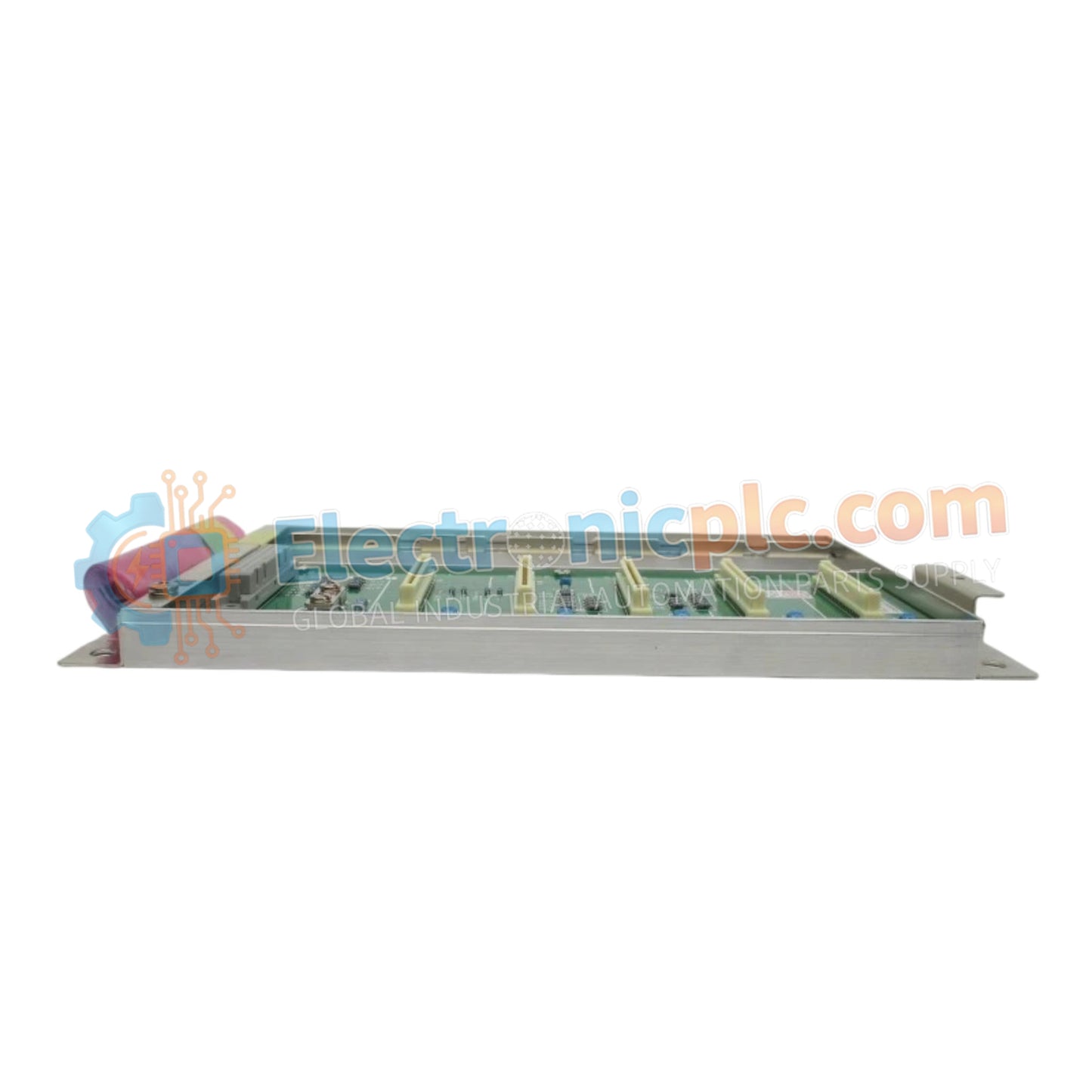
The YOKOGAWA NFBU050-S10, also cataloged as the NFBU050 Short Base Module, operates as a dedicated hardware component for field control network mounting within FCN-RTU system platforms. This module provides the mechanical and electrical backplane interface required to host I/O modules in space-constrained industrial control cabinets.
The NFBU050-S10 signifies a specific base unit configuration optimized for Yokogawa FCN-RTU architectures. The "S10" suffix designates the standard short-form base design, which accommodates a limited number of module slots compared to full-length base plates, facilitating high-density installation in standardized 19-inch racks or localized enclosures.
| Parameter | Specification |
| Model | NFBU050-S10 |
| Brand | YOKOGAWA |
| Origin | JAPAN |
| Weight | 1.5 kg |
| Dimensions | 130 mm x 142.5 mm x 65.8 mm |
| Operating Temp | -20 deg C to 70 deg C |
| Power Consumption | 20 W max |
| Altitude | Up to 3000 m |
| Mounting | DIN rail or 19-inch rack |
The NFBU050-S10 utilizes internal backplane bus protocols to support module communication within the FCN-RTU architecture. It facilitates seamless signal distribution for modules supporting 4-20 mA HART loop protocol connectivity, ensuring that field data is transmitted with low latency to the CPU. The mechanical design enforces channel-to-channel isolation through strategic board layout, preventing signal crosstalk during high-speed data acquisition cycles.
Q: Is this base module compatible with hot-swap operations for connected I/O modules?
A: The NFBU050-S10 supports the removal and insertion of compatible I/O modules under power, provided the FCN-RTU system configuration allows for hot-swapping in the current state. Ensure all latching mechanisms are fully engaged to maintain backplane contact integrity.
Q: Can the base module be mounted directly in high-vibration areas?
A: Yes, the module is constructed for mounting on standard DIN rails or 19-inch racks. For high-vibration environments, verify that the DIN rail clips are locked and that the base is secured to the enclosure backplane at all designated mounting points to mitigate mechanical fatigue.
Verify the mounting surface is flat and free of debris. If installing on a DIN rail, ensure the rail is securely fastened to the cabinet chassis to provide an adequate ground reference.
Align the base module with the mounting rail and press firmly until the locking mechanism clicks into place.
When installing modules into the base, ensure alignment with the backplane connectors. Apply even pressure to the module faceplate until it is flush with the base.
Tighten all retention screws on the module faceplates to ensure optimal mechanical stability and electrical grounding to the base chassis.
Confirm that the power supply to the base unit is within the specified range before engaging the system. Check for proper bus voltage levels across the backplane terminals.


