My Cart
0 items
Genuine Automation Parts | Worldwide Express Delivery | 12-Month Warranty — [GET A QUOTE]

Configured for high-density I/O mounting in STARDOM FCN/FCJ controller architectures, the YOKOGAWA NFBU200-S10 S1 (NFBU200 Base Module) provides direct physical execution of backplane bus distribution and module connectivity.
Availability: In stock
Reliable Worldwide Delivery
30-Day Money-Back Guarantee
Need more details? Read our fullShipping PolicyandRefund Policy.


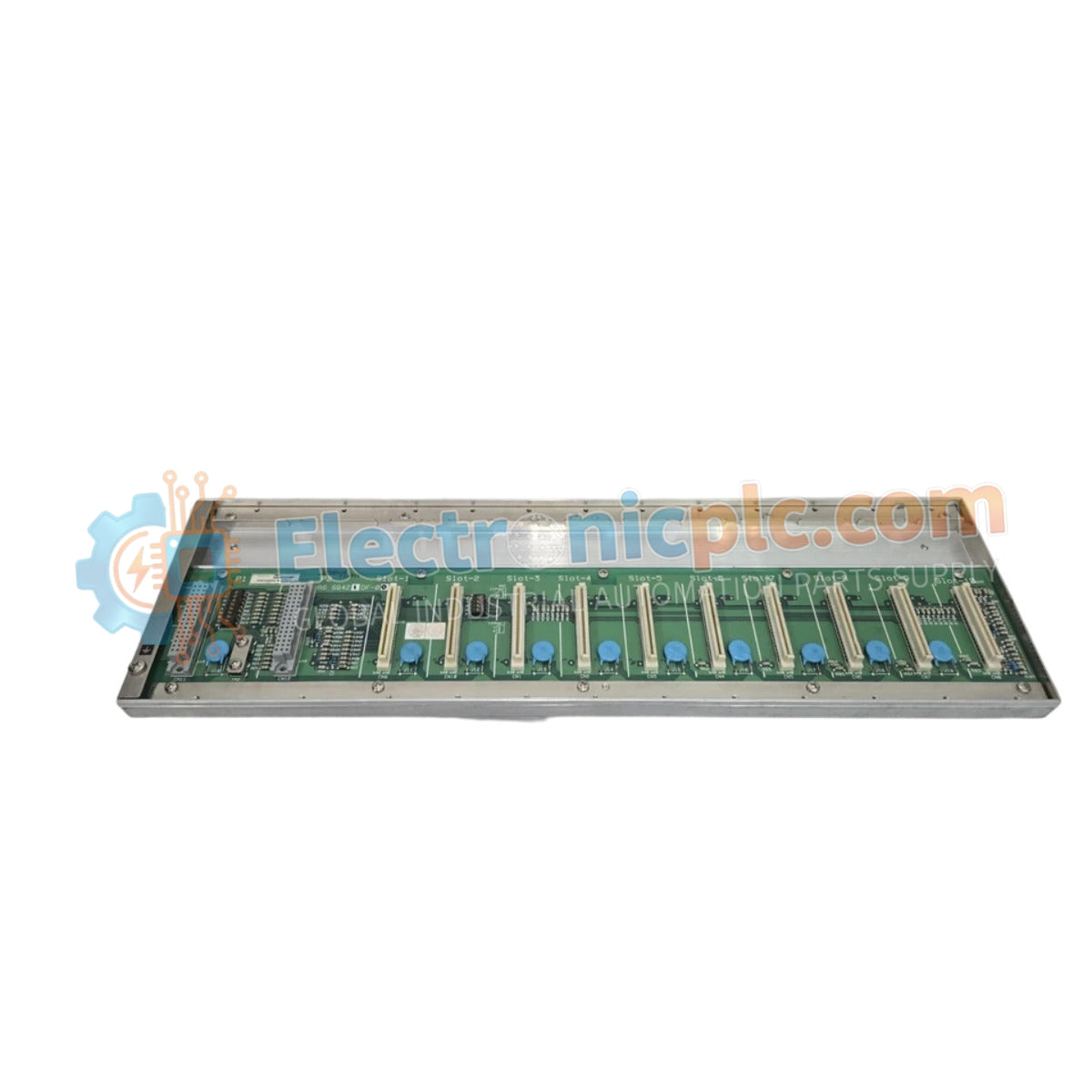
Configured for high-density I/O mounting in STARDOM FCN/FCJ controller architectures, the YOKOGAWA NFBU200-S10 S1 (NFBU200 Base Module) provides direct physical execution of backplane bus distribution and module connectivity.
The NFBU200-S10 S1 utilizes a specific ordering matrix to identify hardware compatibility. The -S10 designator represents the base module configuration for local I/O expansion, while the S1 suffix denotes the revision iteration, ensuring compatibility with specific STARDOM backplane bus communication protocols and firmware versions.
| Parameter | Specification |
|---|---|
| Model | NFBU200-S10 S1 |
| Brand | YOKOGAWA |
| Origin | Japan |
| Weight | 2 kg |
| Dimensions | 2.2 cm x 12.4 cm x 12.6 cm |
| Operating Temp | 0 deg C to 60 deg C |
| Power Consumption | Passive (backplane powered) |
| Module Type | Base Module |
| Mounting Interface | DIN-rail or rack-mount |
The NFBU200-S10 S1 serves as the mechanical and electrical foundation for I/O modules within the STARDOM environment. It facilitates the backplane bus communication required for deterministic data exchange between the CPU and field I/O. The module architecture is designed to support high-speed FOUNDATION Fieldbus and analog loop connectivity, ensuring that signal routing remains isolated from electromagnetic interference through an optimized internal trace layout.
Q: Is the NFBU200-S10 S1 compatible with all STARDOM I/O modules?
A: The NFBU200-S10 S1 is compatible with designated STARDOM I/O modules that utilize the standard backplane interface. Refer to the specific I/O module datasheet to verify mechanical and electrical compatibility before installation.
Q: Can this base module be expanded using extension cables?
A: Yes. The base module supports integration with STARDOM expansion cables to extend the I/O bus to remote racks, provided the total bus length remains within the defined electrical signal propagation limits of the control system.


