Skip to product information
1 of 3

NFBU200-S15 Base Module YOKOGAWA

NFBU200-S15 Base Module YOKOGAWA

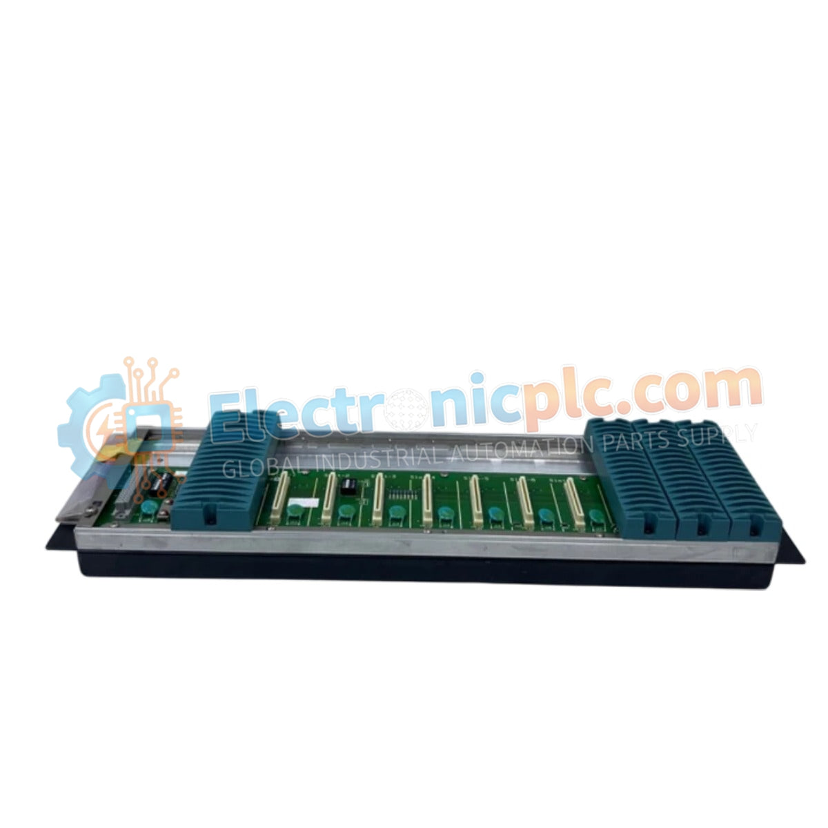
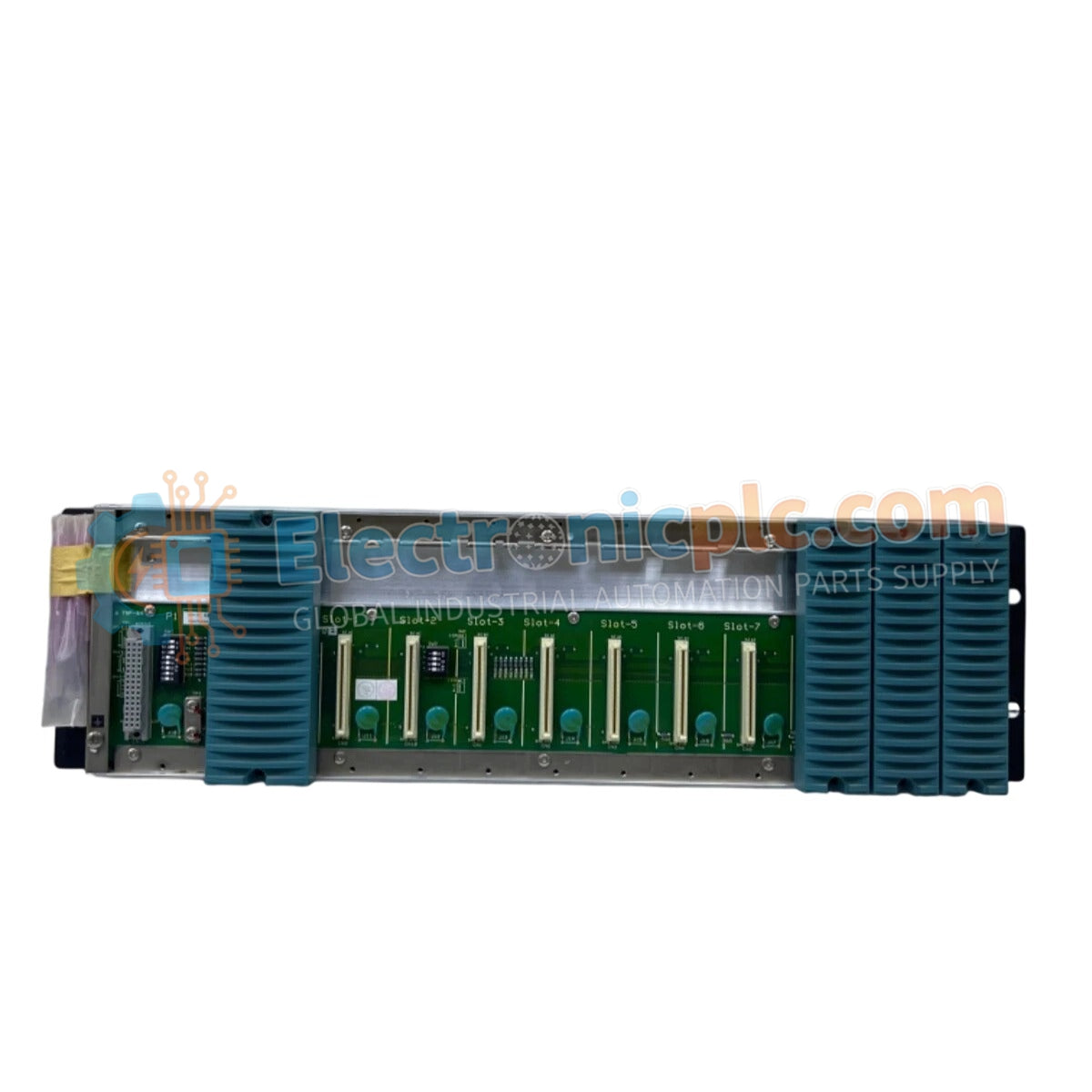
Configured for high-density I/O integration in field control stations, the YOKOGAWA NFBU200-S15 (NFBU200 Base Module) provides direct physical/electrical execution. This hardware component serves as the primary mounting and backplane interface...

17 people are viewing this right now

AvailabilityIn stock

SKU: NFBU200-S15
Vendor: Yokogawa
Category: Base Module
Related Series:

Shipping & Returns

Reliable Worldwide Delivery

  • Carriers: Shipped via DHL, FedEx, UPS, or USPS.
  • Dispatch: Orders processed in 1-2 business days and dispatched within 3-5 business days.
  • Tracking: Full tracking details provided via email upon shipment.

30-Day Money-Back Guarantee

  • Guarantee: 30-day return window for in-stock, factory-sealed products.
  • Condition: Items must be unopened, unused, and in original packaging.
  • Authenticity: We guarantee 100% original and authentic hardware.

Need more details? Read our fullShipping PolicyandRefund Policy.
Authenticity & Warranty

  • Genuine Guarantee: We supply only 100% original, brand-new, and factory-sealed industrial automation parts.
  • Full Coverage: Every component is backed by a 12-month comprehensive warranty from the date of purchase.
  • Traceability: All products come with original factory documentation and accessories for full industrial compliance.

Technical Support & Sourcing

  • Expert Assistance: Our technical team provides free consultation to help you verify compatibility for DCS and PLC systems.
  • Rare Part Sourcing: Specializing in obsolete and hard-to-find components from Allen-Bradley, Siemens, ABB, HIMA, and more.
  • Bulk Inquiries: Contact us at pambo@5gplc.com for volume pricing or customized project quotes.
View full product details

Configured for high-density I/O integration in field control stations, the YOKOGAWA NFBU200-S15 (NFBU200 Base Module) provides direct physical/electrical execution. This hardware component serves as the primary mounting and backplane interface utilized to execute power distribution and signal routing across the internal SB Bus for FIO-compliant control platforms.

Suffix Breakdown & Model Matrix

  • NFBU200: Base unit model for DIN rail-mounted I/O infrastructure.
  • -S: Standard hardware configuration variant.
  • 1: Mounting type specified for DIN rail attachment.
  • 5: Basic hardware level, non-explosion-proof rating.

Hardware Specifications

Parameter Specification
Model NFBU200-S15
Brand YOKOGAWA
Origin JAPAN
Weight 3.0 kg
Dimensions Standard NFBU Chassis
Operating Temp -20 to 70 deg C
Power Supply Slots 2
I/O Slots 10
SB Bus Duplex

Field Control Station Architecture and Bus Integrity

The NFBU200-S15 utilizes a duplexed SB Bus to maintain communication availability between the CPU modules and the mounted I/O modules. The backplane design supports flexible power supply configurations, allowing for either single or duplexed power modules to ensure operational uptime. In a single CPU configuration, the base module accommodates up to 8 I/O modules, whereas a duplexed CPU configuration supports up to 6 I/O modules to account for the increased overhead of the redundant processing architecture.

Frequently Asked Questions

Q: Can the NFBU200-S15 support mixed CPU redundancy modes?

A: The capacity of the base module changes based on the CPU configuration; ensure that the I/O module count (max 8 for single, max 6 for duplex) is strictly observed to avoid exceeding the backplane power or communication bus limitations.

Q: Is the NFBU200-S15 compatible with non-DIN rail mounting applications?

A: No, the "1" suffix in the model string denotes a DIN rail-mounted unit; verify that your cabinet layout includes the appropriate rail infrastructure for secure installation.

Field Installation Guidelines

  • Mount the NFBU200-S15 on a rigid, vibration-resistant DIN rail system to ensure the backplane remains level and secure during operation.
  • Verify the power supply voltage (typically 24 VDC) before seating the power modules into the two designated slots to prevent short-circuiting the SB Bus.
  • Ensure all I/O modules are fully seated and the mechanical locking levers are closed, as incomplete engagement can lead to intermittent signal loss on the duplexed SB Bus.
  • Maintain a minimum clearance distance from other heat-generating equipment to comply with the -20 to 70 deg C environmental requirements.
  • Perform a grounding check on the chassis earth terminal to ensure the module frame is properly bonded to the cabinet ground bus, mitigating electromagnetic interference.