
My Cart
0 items
Genuine Automation Parts | Worldwide Express Delivery | 12-Month Warranty — [GET A QUOTE]

Configured for local bus extension in STARDOM control systems, the Yokogawa NFCB301-C100 (NFCB301-C100 SB Bus Cable / Local Bus Extension Module) provides direct physical/electrical execution of controller-to-I/O communication pathways.
Availability: In stock
Reliable Worldwide Delivery
30-Day Money-Back Guarantee
Need more details? Read our fullShipping PolicyandRefund Policy.
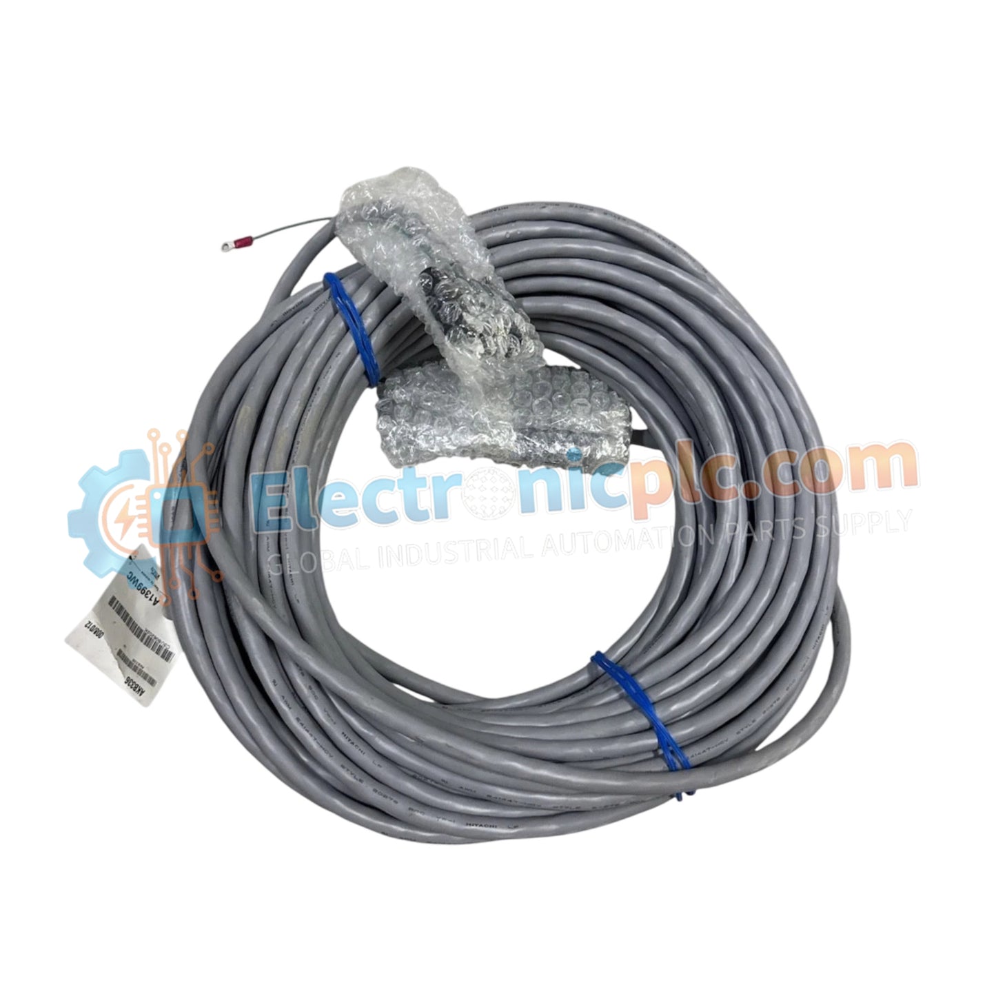
Configured for local bus extension in STARDOM control systems, the Yokogawa NFCB301-C100 (NFCB301-C100 SB Bus Cable / Local Bus Extension Module) provides direct physical/electrical execution of controller-to-I/O communication pathways.
| Parameter | Specification |
|---|---|
| Model | NFCB301-C100 |
| Brand | Yokogawa |
| Origin | Japan |
| Weight | 0.4 kg |
| Dimensions | Standard STARDOM Cable/Module Form Factor |
| Operating Temp | -20 deg C to 70 deg C |
| Power Consumption | Backplane bus powered |
| Compatibility | STARDOM FCN-100, FCN-500, FCJ, FCN-RTU |
| Duplexing | Supported (CPU, Power, SB Bus, Network) |
| Memory Protection | ECC (Error Correction Code) |
The NFCB301-C100 is engineered to maintain high-speed deterministic data transfer across the STARDOM control architecture. By providing duplexing support for the CPU and power supply, the unit ensures fail-safe state execution during component failure. The SB bus interface utilizes internal self-diagnostics to perform real-time monitoring of signal latency and bus integrity. When deployed, the module supports channel-to-channel isolation on the backplane, protecting the control network from localized electrical faults. Furthermore, the incorporation of ECC memory ensures that all data packets transmitted across the local bus are verified and corrected, maintaining communication reliability without the need for frequent hardware reboots.
Q: Does the NFCB301-C100 support hot-swapping during active operation?
A: Yes. The unit is designed for hot-swapping within duplexed systems. When one path is maintained, the NFCB301-C100 can be extracted and replaced, provided the control system is set to the appropriate maintenance mode to prevent bus collision.
Q: How does the system respond if the SB bus cable experiences a partial connection?
A: The onboard RAS (Reliability, Availability, and Serviceability) features monitor the physical layer. If signal degradation is detected, the CPU performs diagnostics and logs a fault, triggering a switch-over to the redundant duplexed SB bus path to maintain control availability.
